This is short how-to, so if you have any questions, please comment below. The prerequisite is loaded Qczek LRS 2.0 firmware to both modules TX and RX.
TX module configuration
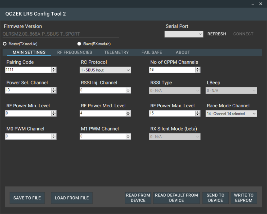
To enter configuration mode, you have to connect M1 to GND. After powering up, module LED should blink slow. Then you have to connect your USB->Serial adapter’s RX pin to TX pin of the module, and USB->Serial adapter’s TX pin to RX pin of the module, or to AUX pin of the module which is used for soft serial. Then you have to run configuration tool for QLRS 2 (it’s different then for 1.x versions).
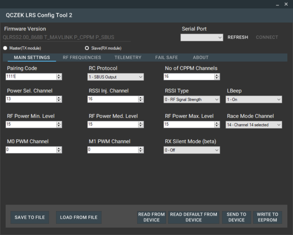
Special function would be controlled by following channels:
- 13 – RF power (TX and RX)
- 14 – Race mode (TX and RX)
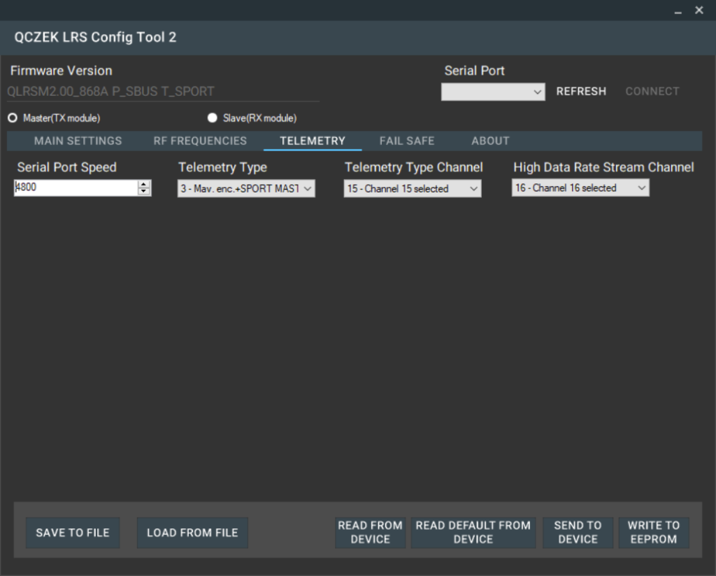
- 15 – Telemetry type (TX and RX)
- 16 – High data rate (TX only)
- 16 – RSSI level (RX only)
RX module configuration
To enter configuration mode, you have to connect M1 to M0. After powering up, module LED should blink slow. Then you have to connect your USB->Serial adapter’s RX pin to TX pin of the module, and USB->Serial adapter’s TX pin to RX pin of the module.
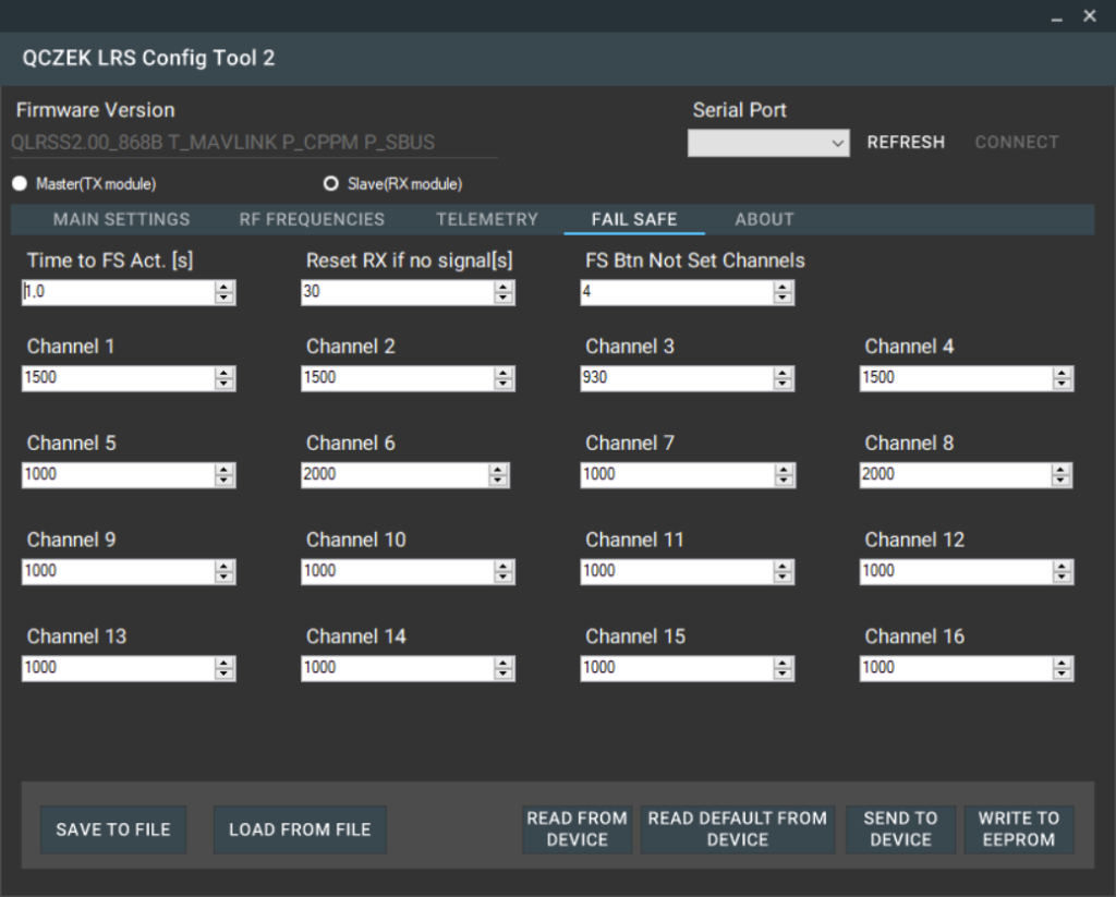
RX configuration looks like following:

Radio setup
Now you have to connect TX module to your radio. Connection should be like following.
- M0 -> LED
- M1 – micro switch
- AUX -> Bluetooth TX (Bluetooth set to 4800bps)
- TX – > Bluetooth RX (Bluetooth set to 4800bps)
- RX -> SBUT ouput of your radio. Please note that voltage level from Taranis radio are too high, but to be honest it’s working fine 🙂 But my advice is to use voltage divider or inverter.
- VCC -> +5v from BEC
- GND -> GND
If you don’t want to use inverter you can setup sbus output no in inv.

For encapsulated telemetry you can setup constants values to channels: 14,15,16. Channel 13 is used to change RF power

Model setup
Now you have to connect your APM FC to your RX module
- MO->LED
- M1 – not connected
- AUX -> FC SBUS input
- TX -> FC RX telemetry port
- RX -> FC TX telemetry port
- VCC -> +5V
- GND ->GND
APM Configuration
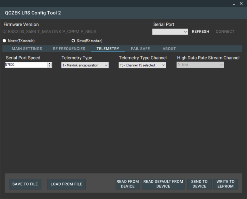
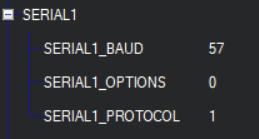
The first thing is setup correct serial port speed for telemetry port (57600), ant telemetry type to mavlink.
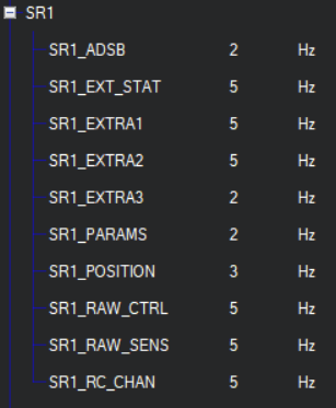
Then you have to limit frequency of mavlink messages. Qczek LRS’s stm8 MCU is not power enough to process it fast enough…
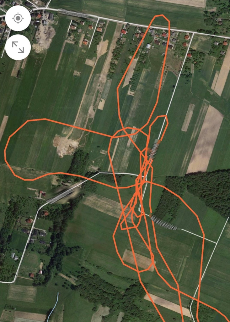
Now you should be able to connect any mavlink client to track your plane.
This is screen shot from old android app called Mission Maker
Modes
- Race Mode – makes possible sending data almost twice faster then standard mode, but rx sensitivity is 3dB less
- Telemetry type/Telemetry type Channel – it used to convert mavlink telemetry to internal Qczek LRS telemetry stream and back to mavlink on ground. It can be switched on/off permanently, or using on of the RC channels. When switch is off, raw data are transferred, so it makes possible to use APM ground station to setup parameters/mission, and then switch to mavlink encapsulation and make a mission. This feature is more experimental then useful, and would work better with support from FC/ground station software. I’m going to take care about it.
- High data rate – this switch controls what kind of data frames are send and what is frequency of sending. Channels’ values are not all send in single frame, but in defined sequence. The standard sequence looks like following:
- FRAME_TYPE_CHN_1_4,
- FRAME_TYPE_CHN_5_8,
- FRAME_TYPE_CHN_1_4 | FRAME_TYPE_REQEST_TELEMETRY,
- FRAME_TYPE_CHN_9_16,
- FRAME_TYPE_CHN_1_4 ,
- FRAME_TYPE_STREAM_TX_RX | FRAME_TYPE_REQEST_TELEMETRY
It means that channels 1 to 4 are send almost 3 times more frequently then channels 5 to 8 and 9 to 16. Also telemetry data are transferred from AUAV to ground only twice per sequence’s run. You also need to know that channels 9 to 16 are transferred as 5 bits values, so they can have only 32 values, not very suitable for control surfaces, but good enough for switching flaps, camera, osd, etc.
When high data rate is switched on, after every sequence run, 40 telemetry transfer occurs:
FRAME_TYPE_STREAM_TX_RX | FRAME_TYPE_REQEST_TELEMETRY
But when there is no data to be send from TX to RX, the transfer is like following
FRAME_TYPE_CHN_1_4 | FRAME_TYPE_REQEST_TELEMETRY,
The high data rate mode is useful together with telemetry type switch, you can turn on high data rate, switch off telemetry encapsulation and try raw mavlink connection.