I try to switch with all my 1.3GHz FPV stuff to 5.8GHz band, but unfortunately my NWT4000 analyzer has 4.4GHz limitation, and spending 500 baks for measuring view antennas, it’s not good idea… so why not to use cheap 5.8GHz VTX controlled via smart audio protocol together together with RF power meter, directional coupler and small Arduino board to control every components. And here we have …
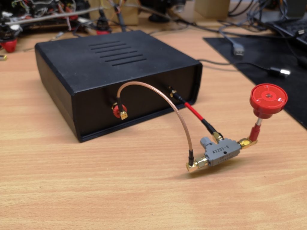
Looks good, doesn’t it? So if you want to build it you can read more.
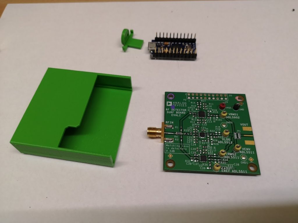
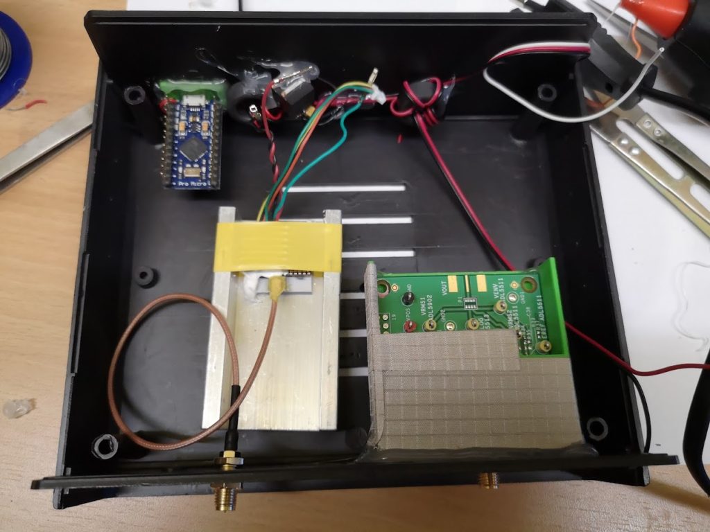
Firs you need to collect necessary parts:
- arduino Pro Micro or similar
- RF power meter board equipped with ADL5902 or similar chip
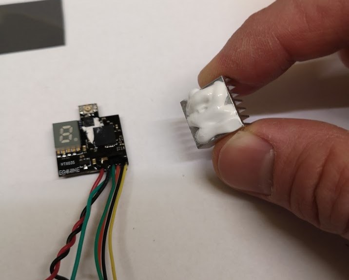
- low power 5.8GHz VTX controlled via smart audio protocol. I grabbed Eachine VTX03S, but you can use other
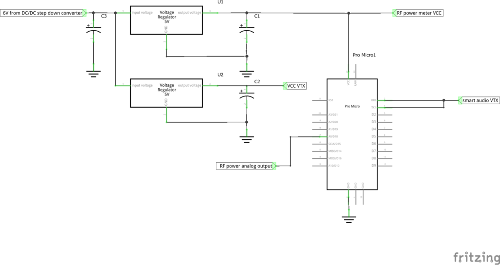
- DC-DC Converter Step Down Module
- 2 pieces of L.D.O Voltage Regulators (like LM2915), capacitors, wires, plastic or better metal case to put everything inside, RF shielding tape, end others
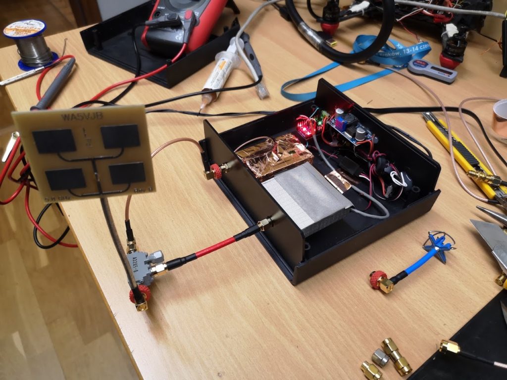
Now you need to connect everything, the power supply should have abut 6-7V, if higher it’s recommended to use DC/DC switching step down converted to avoid overheating analog voltage regulators. There are separated regulators for arduino board and RF power meter kit and for VTX to avoid interferences. Please don’t power your stuff from USB, it’s not good idea, the voltage is very unstable, the measurement will be worst then you can imagine…
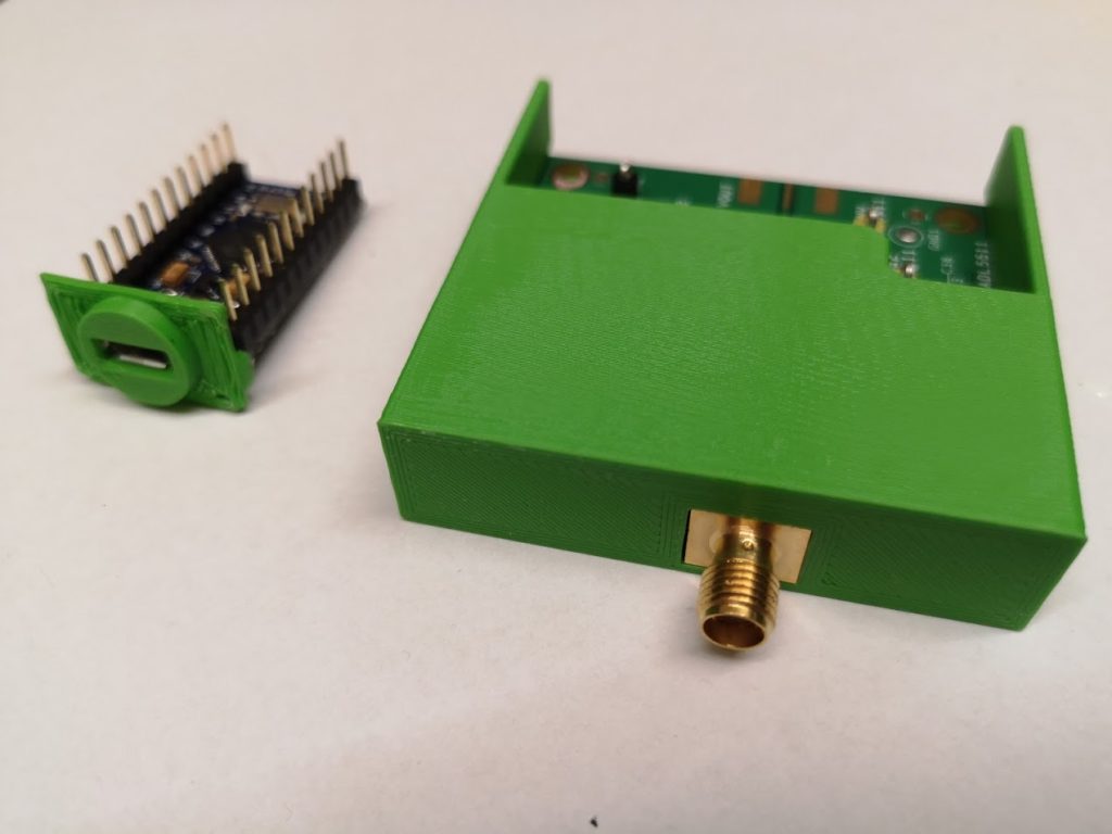
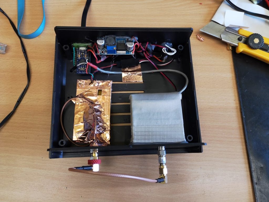
I designed 3d printed parts to mount RF meter kit and arduino and adhesive shielding tape to keep interferences away as much as possible…
The VTX’s mounted inside heat sink to keep it cool without air flow which is normal when it’s mounted on RC plain
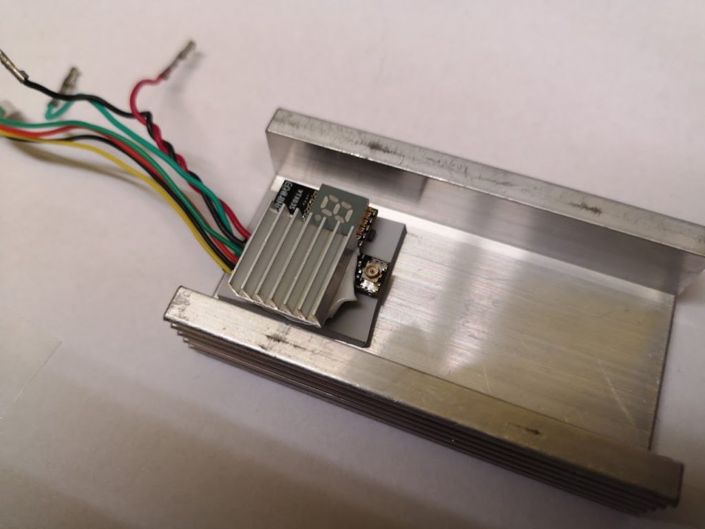
And maybe it’s not perfect, but good enough for hobby purpose.
Now it’s time to connect to PC. I’m too lazy to build pro app, but quick and dirty Arduino sketch does good job. The smart audio protocol implementation is based on https://github.com/NightHawk32/SmartAudio-testing. It’s my very first Arduino project, fill free to make better 😉 you can simply download it and run. (of course to measure antennas resonance frequency you need directional coupler) .
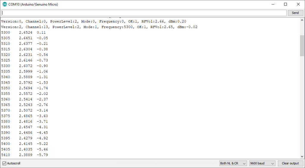
There are not too much options, everything is controlled using serial monitor.
- z to v change power output
- 1 or 2 change frequency to two predefined values
- g – do the scan.
You should do the scan using lowest possible RF power, to avoid burning your RF meter. Please check what are max values for the rf meter you have and use attenuators if required.
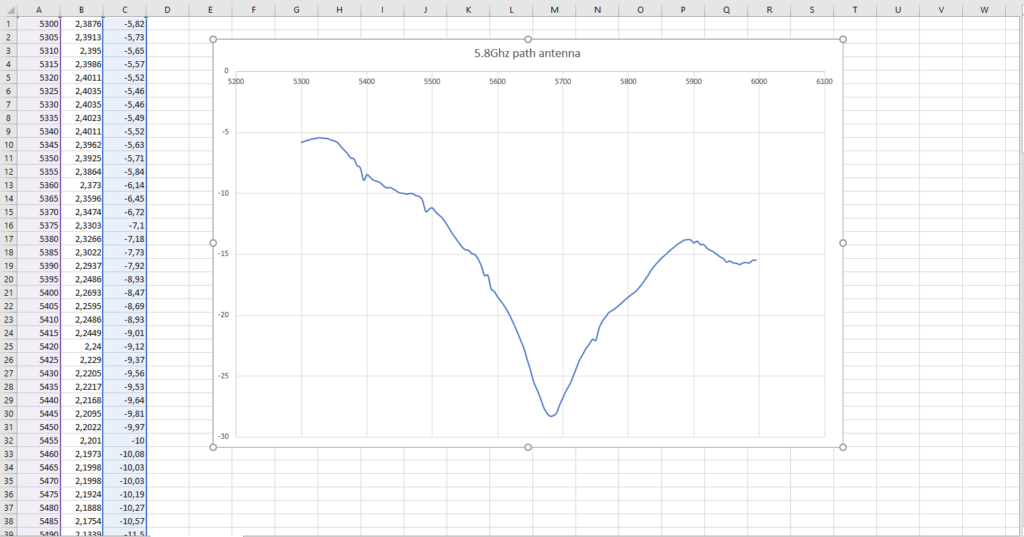
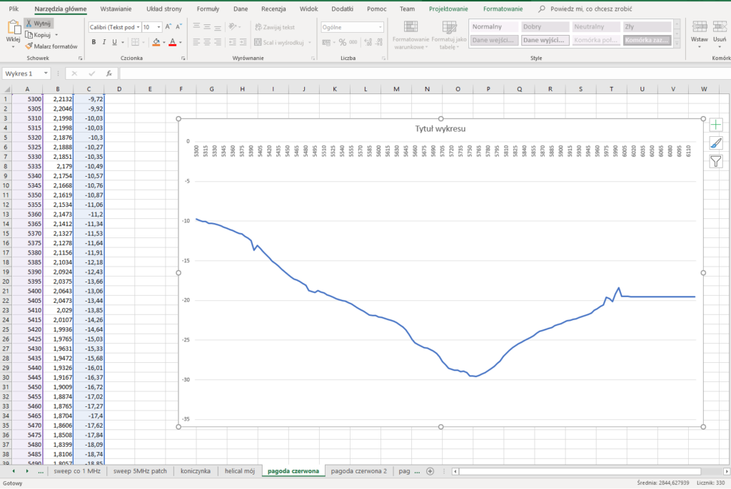
Next you can visualize output using excel, or open office.
That’s all, I’m waiting for your feedback 🙂