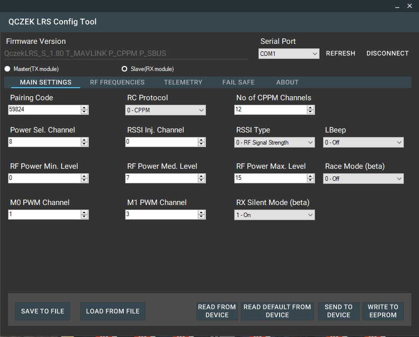
Thanks to Mosvov we have multiplatform configuration tool ready!
https://github.com/mosvov/qczek-modules-setting
Beta version of configuration tool is ready for download.
Serial Terminal based configuration.
Settings mode is only available, when M1 pin is connected to ground – for TX modules, or M0 is connected to M1 – for RX modules. during powering on. So you have to press switch located on your TX module before you start your TX (M1 to GND), or connect M0 to M1 on your RX module before you connect it . The settings mode is indicating by slowly blinking led (instead of fast twice a second blinking in normal operation mode).
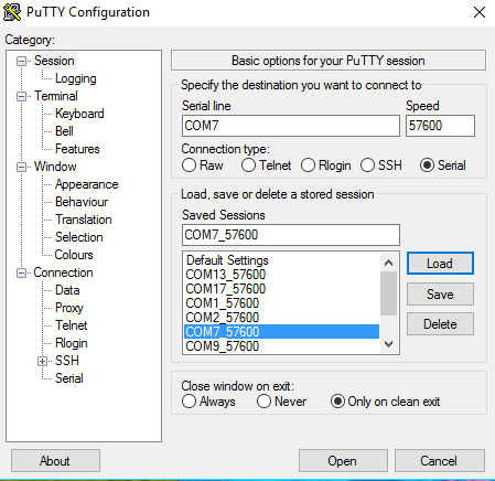
Now you have to use putty or any other terminal to connect your device. The speed is always 57600, and could not be changed now.
Now you have to type, or better copy paste command to change module’s settings.
There is small issue with serial port DMA processing, so sometimes, you have to press space or enter key several times after typing every command. Is because DMA buffer is processed every 10 chars, and if you type let say 7 chars, it will wait … but don’t worry 🙂
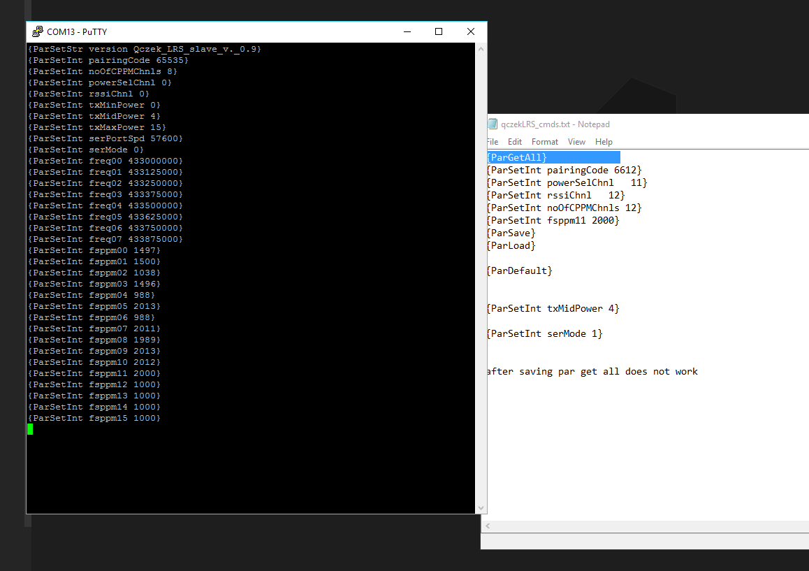
First you can start with {ParGetAll} – it will display current settings.
Please note that from version 1.10 due to flash memory limits, functionality is split to different images supporting different features, so if you want to use mavlink telemetry flash mavlink, if ublox flash ublox marked image.
Please also remember that even when you select correct image, you HAVE TO enable feature using corresponding paramter!
Additionally there is info parmeter containing all supported features, eg.
{ParSetStr f. P_CPPM P_PXX }
So what could be set and how 😉 Please note that from version 1.00 almost all parameters have new names placed in [].
-
-
- version [v.] – it’s read only value, you can’t set it
- f. – features (read only)
- pairingCode [pCode] – range: 0 to 65535. It’s code used for pairing your devices, it should be the same for master and slave unit.
- noOfCPPMChnls – range 8-16. Number of CPPM channels. Starting from version 0.91 if it’s set to 0 on slave site, first channel value will be output as standard 50Hz servo PPM signal. It make possible to control single servo directly from receiver.
- powerSelChnl [pwrSelChnl] – range 0-16. If 0 – this feature is disabled and max power is used. In other cases selected channels is used to switch between defined power settings
- rssiChnl – range 0-16. If 0 – this feature is disabled. This channel will be overwritten by rssi value (aka rssi injection). It works only on slave module.
- txMinPower, txMidPower, txMaxPower – range 0-15, 0 is min 200mW 15 is max 1000mW. It’s not linear, so you have to check what is the power for other values (for 4 is something around 500mW). You can setup different values for master/slave unit.
- serPortSpd – speed of serial port, suported from version 0.91, for v. 0.9 it’s always 57600.
- serMode – you can choose, how serial data is transferred, 0 – transparency mode, 1 – mavlink telemetry encapsulation. From version 0.91 2 – uBlox GPS telemetry is available. Starting from version 1.90 you can set TX to mode 3 – Mavlink enc. + SPORT which force it to convert mavlink telemetry to FrSky S.PORT telemetry available on PIN M0.
Following settings are allowed.- RX 0, TX 0 – transparency mode, bytes are just send from RX to TX and from TX to RX.
- RX 1, TX 1 or 3 or 4 – mavlink messages are converted by RX device to internal telemetry protocol, transferred to TX device and converted back to mavlink messges and to sport telemetry (when 3 or 4 selected).
- RX 2, TX 1 or 3 or 4 – GPS uBlox stream is converted by RX device to internal telemetry protocol, transferred to TX device and converted back to mavlink messges and to sport telemetry (when 3 or 4 selected).
- freq00 [fr00] – freq07 [fr07] – range 420000000 – 45000000 – range hopping frequencies. Must be the same for master/slave unit. Please remember to keep 250khz difference between any channels, they can’t overlap.
- fsppm00 [fs00] – fsppm15 [fs15] – range 800-2200 channels’ fail save values. It could be also saved by pressing longer then 10 seconds button on TX module (master module)
-
timeToFS – from version 0.91 you can set time to fail safe activation. It’s set in tenths of second (default value = 20 -> 2s to fs activation)
-
proto – from version 1.00 you can choose input protocol for master module (TX module) 0 – CPPM, 1 – PXX XJT D8/D16, from version 1.10 for slave (RX module) 0 cppm, 1 – sbus. From version 1.80 it’s SBUS input implemented for TX board. Just set proto = 2, and connect SBUS data cable via external inverted to RX pin. In this case, TX pin works as software serial port (for telemetry) but it’s speed is fixed to 57600.
-
rssiT – from version 1.00 you can choose how RSSI is calculated, 0 – old way based on signal strength, 1 – based on SNR level, 2 -package lost based – it’s only for slave module
-
lbeep – from version 1.10 you can enable lbeep signal on rssi pin 0 – rssi PWM, 1 – lbeep – it’s only for s slave module
-
racem – from version 1.50 you can enable race mode (0 – standard mode, 1 – race mode)
-
wdTime – from version 1.50 you can decide how long watch dog will wait to reset RX in case of sync lost. Default value 30s.
-
fsDontT – from version 1.50. Bit mask defining which channels’ fail safe values will not be set by long (10s) button press. You can always set all the values by configuration tool. For keeping fail save value for throttle (3th channel) just enter 4, and it will be kept as set by configuration tool, even when you long press TX button, to set other channels fs values. If you want to prevent overwriting more channels just enter sum of 2^(no_of_chn-1) let say for channel 1 and 3 and 8 enter 1 + 4 + 128 = 133.
- m0PWMChn – range from 0 to 16. From version 1.80 your RX can output pwm to control servo on pin M0 or M1. If M0 or M1 pin is in use, lBeep nor RSSI pwm does not work.
- m1PWMChn – range from 0 to 16. From version 1.80 your RX can output pwm to control servo on pin M0 or M1. If M0 or M1 pin is in use, lBeep nor RSSI pwm does not work.
- silent – 0 or 1. from version 1.80 you can disable sending any RF signal by RX. Please note that it does not change RC update rate.
- beaFreq – 0 or range 420000000 – 45000000. from version 1.81 you can enable simply beacon, which will send 3 beeps, just after restarting RX if RF signal is lost. When 0 it’s disabled
-
And few new parameters related to adaptive telemetry rate (only for master module) – from version 1.00.
-
devThrs – now system can decide how to utilize limited band, if it’s better to transmit telemetry data from UAV to ground station, or maybe it’s better to send RC channels from ground station to UAV. Till version 1.00 every frame from ground to UAV was followed by receiving telemetry frame. Now system calculates standard deviation from sum of first four channels (yes i know, it should be calculated for every channel separately, but limits of flash/ram do not allow to do it…). It’s based on latest 10 channels value. If you don’t touch sticks, or move it very gently, calculated deviation is low, or zero, if you start moving faster standard deviation is higher…Take a look https://www.youtube.com/watch?v=uxh7p7xgOLQSo devThrs defines standard deviation threshold. If deviation is below, telemetry will be requested every sTelFrmR (standard telemetry frame rate) RC channels frames. By default it is set to 1, so if you don’t touch your radio, telemetry will be received after sending every “RC channels” frame.But if calculated deviation will be above defined threshold, telemetry will be received less frequently, every lTelFrmR (low telemetry frame rate) RC channels frames. By default it is set to 16, so after sending 16 frames, single telemetry frame will be received.You can adjust devThrs depending of your needs observing master module LED. If threshold is not reached it blinks after receiving every CPPM/PXX frame. But if threshold is reached (you move sticks quickly) it blinks less frequently.
-
sTelFrmR – standard telemetry frame rate
-
lTelFrmR – low telemetry frame rate
If you want to set value, you have to type {ParSetInt VAL}. You can’t see what you type, so good idea is to put setting’s value to notepad like following {ParSetInt serMode 1} and copy/past it into terminal window.
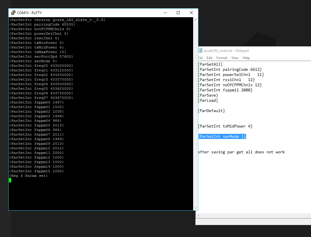
After successful value’s setting you will get {Msg S Pararm set} response 🙂
Now you can configure next value, and when everything is done you can check it using {ParGetAll}.
Now time to save using {ParSave} command. Please remember to press enter several time, till you get info that everything is starred successfully.
After saving parameters, serial interface could stop working (solved in version 1.00) , so you have to disconnect and connect device again. it’s always good idea to check values again!
You can also use {ParDefault} command to restore default configuration or {ParLoad} if you want read not changed values from eeprom.
Now you can power both modules, and you should see fast blinking led on both modules, indicating ppm frames processing :).
If it’s ok, you can set fail save values pressing TX button for more then 10 seconds.