This is QCZEK LRS 🙂
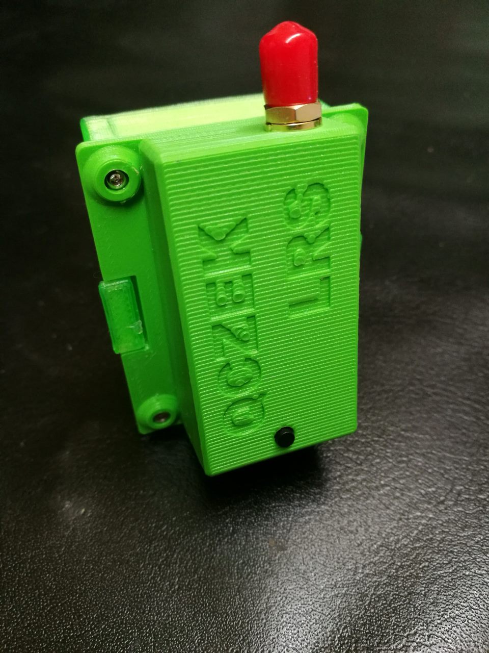
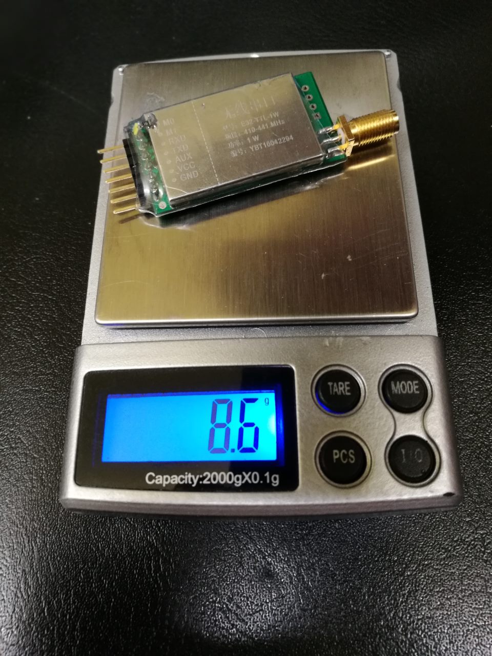
It’s based on LORA SX1278 module (433MHz) , with integrated 30dBm (1W) PA.
My goal’s to create really long distance device with working Mavlink (and others) telemetry.
So main features look like following
- there are two units: master installed in your TX as external module, and slave installed in UAV like any other RC RX.
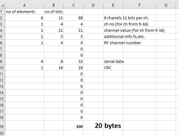
- up to 16 CPPM channels transmitted every 66ms – it’s about 15 Hz (47ms – 21Hz in race mode), more then enough to control AUV with working autopilot. RC channels values are codded using 11 bits. Due to limited band, only first 8 channels are updated at 13Hz frequency, rest of the channels from (9-16, depending on settings) are transferred simultaneously, it means that if you use 12 channels, channels from 9-12 will be transmitted at 13/4(no of additional channels above 4th channel)Hz, it means about 4 times per second. It’s enough to switch flaps, cameras, change flight modes, control gimbal, etc. Additionally thanks to “adaptive telemetry rate“ frames could be send 23 (35 for race mode) times per second 🙂
- additionally, every frame going from ground to UAV can transmit 4 bytes of serial data, it’s not big amount but could be use for different purpose.
- telemetry data is transmitted from UAV to ground station, after reviving every single frame (going from ground transmitter to UAV). There are 11 bytes to be used every frame.
- mavlink telemetry is also supported in limited way. HEARTBEAT, ATTITUDE, POSITION_INT, SYS_STATUS, RC_CHANNELS_RAW messages are packed into raw frames, and recreating on ground site
- RF power could be selected by RC channel’s value or by configuration, to 3 different levels from 200(23dBm) – 1000(30dBm) mW. The power is changing on both units, and levels could be selected differently.
- LORA spread spectrum modulation is used together with frequency hooping technique. There is possibility to choose 8 frequencies around 433Mhz which will be used.
- Receiving sensitivity is -121dBm
- Bandwidth is 250kHz (500kHz for race mode), spreading factor is 7, and coding rate is set 4/8 it means that every single bit of data are codded by two bits. It helps to keep data in good condition 😉
- Time on air is about 24ms, but additional time is spend for switching TX/RX part, enable PA, etc. So total delay is around 30ms.
- Full fail safe support. If RF frame is not received from 2 seconds, defined RC channels values are applied.
- PWM RSSI signal on external M1 pin available. It’s 1.2kHz PMW signal which could be used together wits simply RC filter output analog RSSI voltage.
- lBeep signal on external M1 pin
- RSSI injection into selected RC channel. RSSI level could overwrite selected RC channels, and handled directly by autopilot without additional wiring.
- 16 bit pairing code
- Every frame contains 16 bit CRC to keep consistence.
- Supply voltage 3.3-5.5V voltage higher then 5.5V could burn your module. Recommended voltage is 5V.
List of supported mavlink messages.
- MAVLINK_MSG_ID_RC_CHANNELS_RAW
- MAVLINK_MSG_ID_HEARTBEAT
- MAVLINK_MSG_ID_SYS_STATUS
- MAVLINK_MSG_ID_ATTITUDE
- MAVLINK_MSG_ID_GLOBAL_POSITION_INT
- MAVLINK_MSG_ID_GPS_RAW_INT
- MAVLINK_MSG_ID_VFR_HUD
- MAVLINK_MSG_ID_GPS_GLOBAL_ORIGIN
- MAVLINK_MSG_ID_HOME_POSITION
- MAVLINK_MSG_ID_COMMAND_INT
- MAVLINK_MSG_ID_RADIO_STATUS
And quick look at frame which is send from TX to RX…
Now you can’t wait to build it 😉