Because stm8 based module shortage, and limited flash memory, I decided to move the project to new hardware. My choice fell on E78 868LN22S (and seems to be working also on E78 470LN22S for 433MHz band ) ASR6601 module manufactured by EBYTE. (please note that it must be marked as ASR6601 based, not old one which is not marked and contains ASR6501 chip).
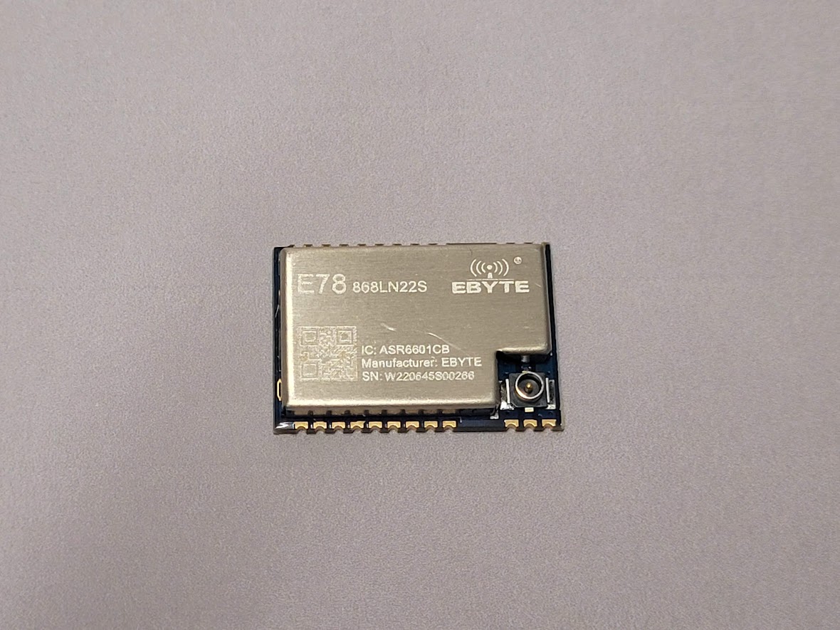
The module has 128 kB of flash memory, 16kB of RAM and it’s powered by 48 MHz ARM Cortex-M4. And of course it contains SX1262 LoRa radio, all in a single chip 22dBm (150mW) of RF power .
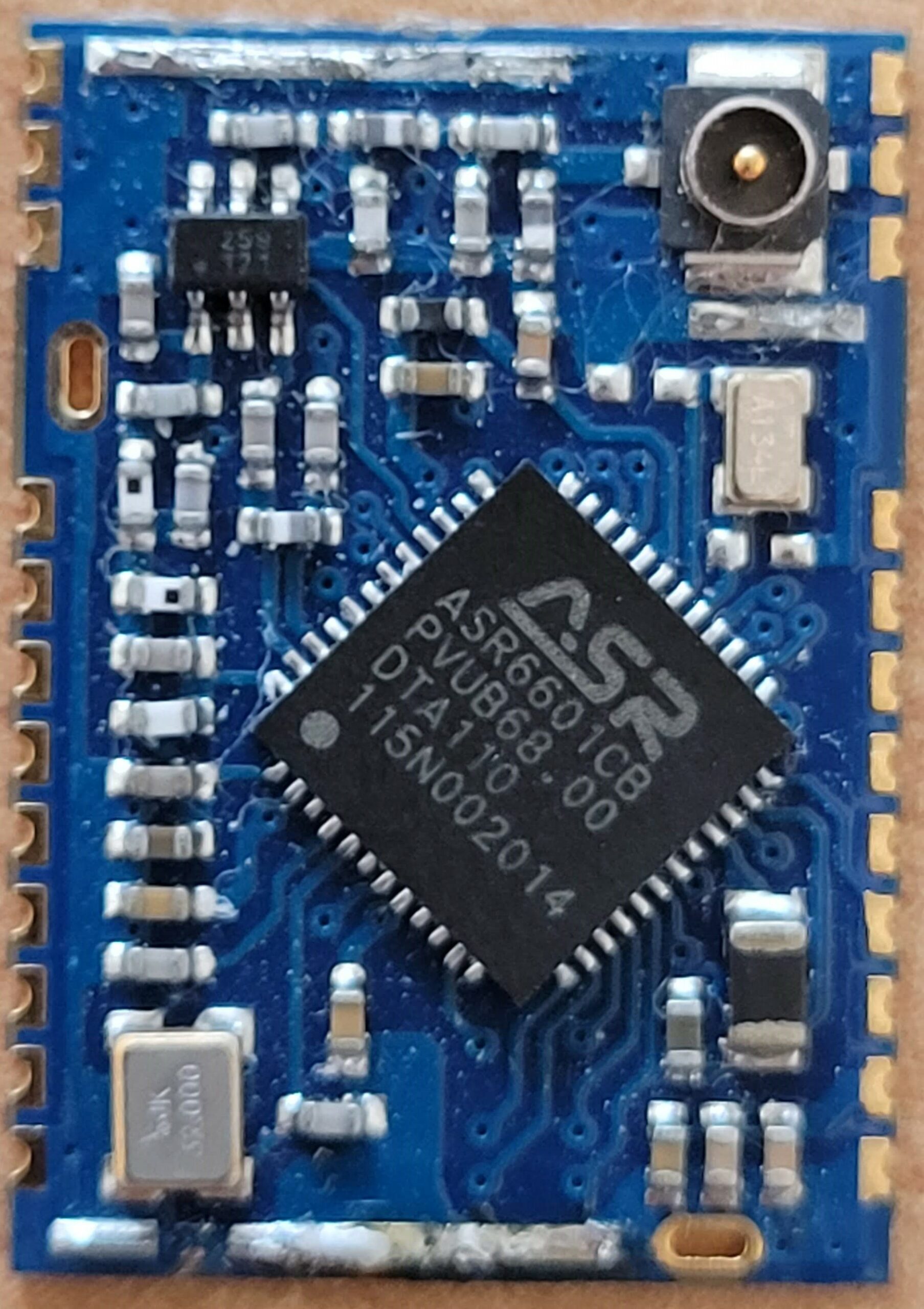
So some reverse engineering was required to find out what are the MCU pin mapping, and how to build a software, but finally there is first version of QLRS RX, which is compatible with legacy STM8 based TX modules. So you can use new ASR based together with your existing old TX module (perhaps 1W ).
Currently the firmware supports only 868MHz band, and limited features. So only CRSF protocol is supported for FC connection, a RSSI is only RF power based, no mavlink and serial mode supported, but it’s enough to find out what is a performance of new hardware.
So, let start to build it.
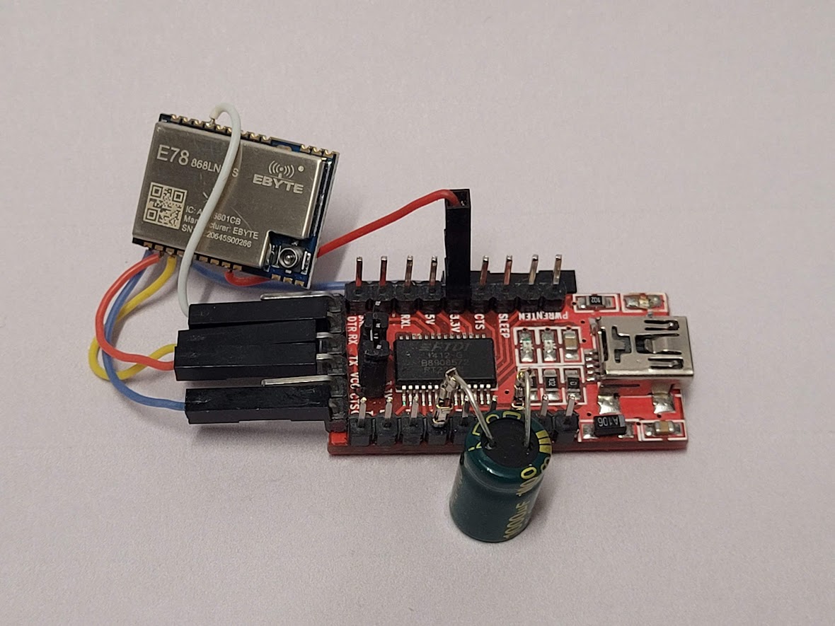
You will need solder a few wires to your module, and remember that max VCC voltage is 3.3V. (I think that 3.9 V is max, according ASR 6601 data sheet).
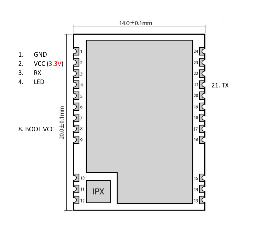
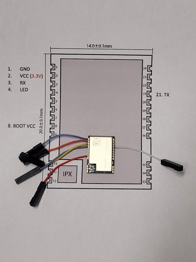
So, then you need USB 2 serial adapter, which supports 3.3V. Please make sure that a VCC selection jumper is set correctly. The connections goes like this:
- module GND -> serial GND
- module VCC -> serial VCC
- module RX (GPIO16)-> serial TX
- module TX (GPRIO17)-> serial RX
- module BOOT (GPIO02) -> serial VCC(3.3V pin)
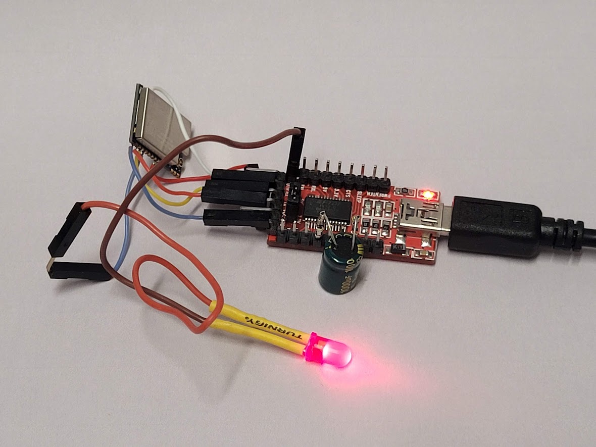
- module LED (GPIO62) to external LED, and another LED pin to serial GND (can be connected later)
- OPTIONAL(if using j-link programmer) – if your module is not responding, it could be in low power mode. Please connect pin no 8 to 3.3V before programming. It should solve the issue.
Additionally i connected 1000uF capacitor, to VCC and GDN of serial interface, because during next step, when we would connect/disconnect the module, it would be required for some PC to not disconnect USB connection due to some voltage drops. But maybe your PC is immune for it.
Now you are ready to upload Qczek LRS firmware. You need to use ASR6601 MultiProgrammer tool and of course QLRS new firmware from download page.
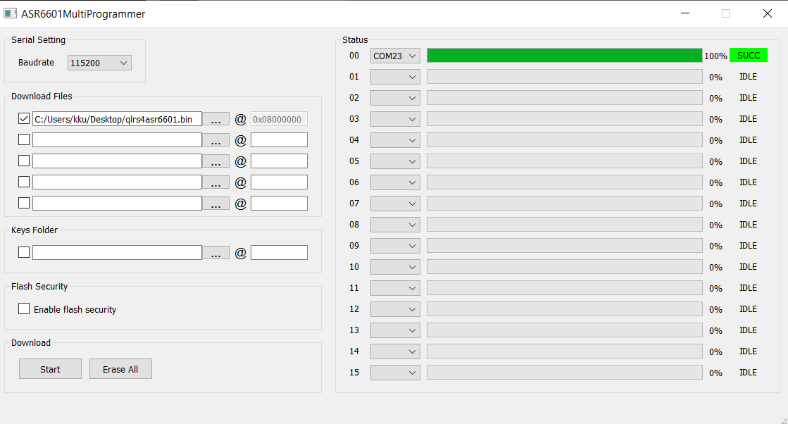
So run the multi programmer select correct com port choose a firmware file…
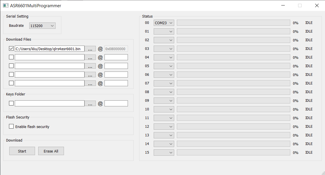
And press start…

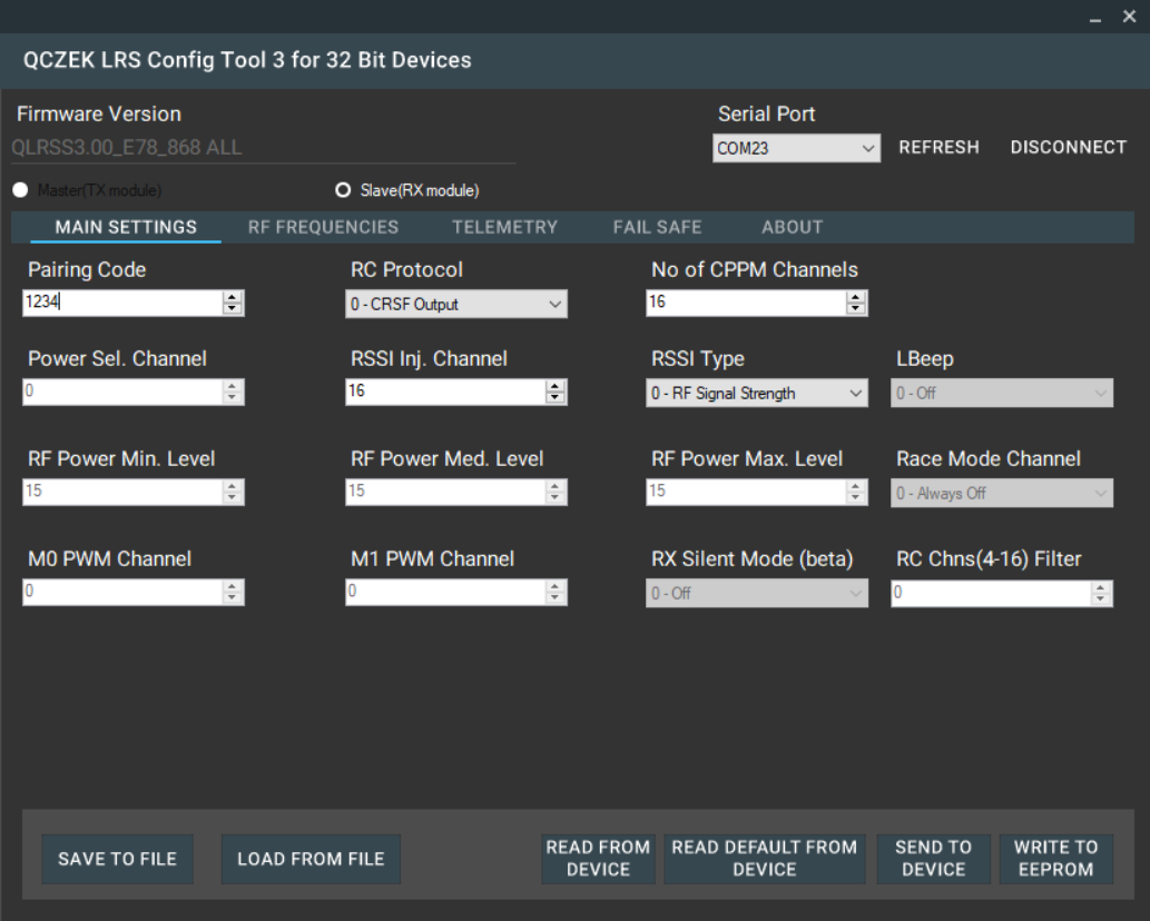
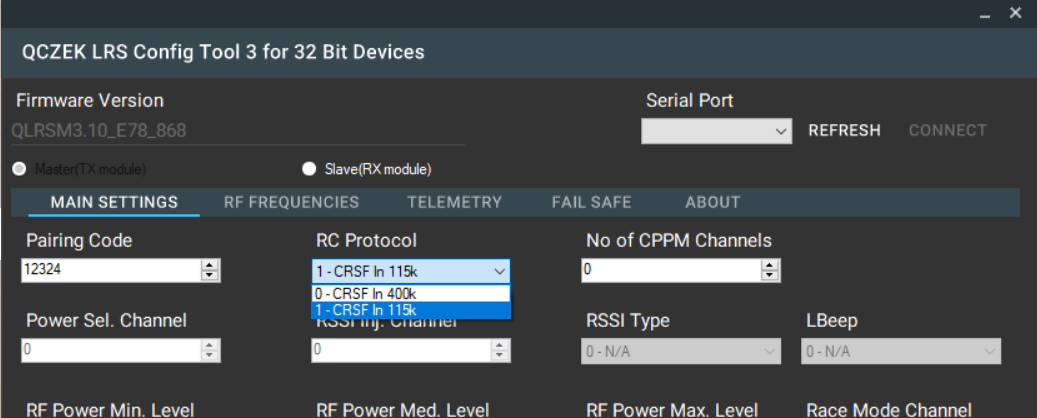
Now time to change the configuration of your new RX. You don’t need to use any M0 to M1 jumpers like for STM8 version, just keep usb 2 serial connected to PC, but disconnect VCC wire from the E78 module. The module should be powered off, but USB serial port should be active. Then run new config tool (from download page), choose correct serial port and press connect. Then you have 15 second to power the E7 module again. Then it will be connected and configuration should be read.
Now you can apply some settings and press send to device, and write to eeprom.
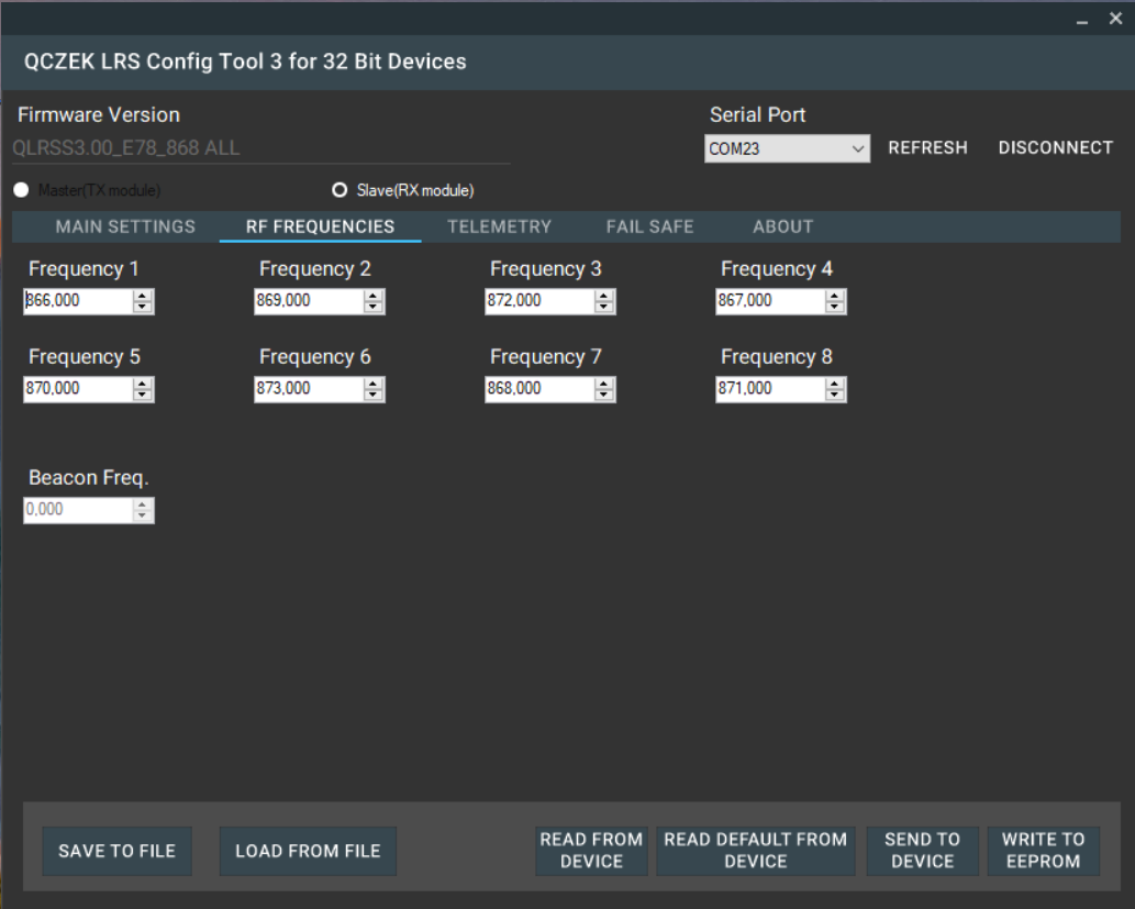
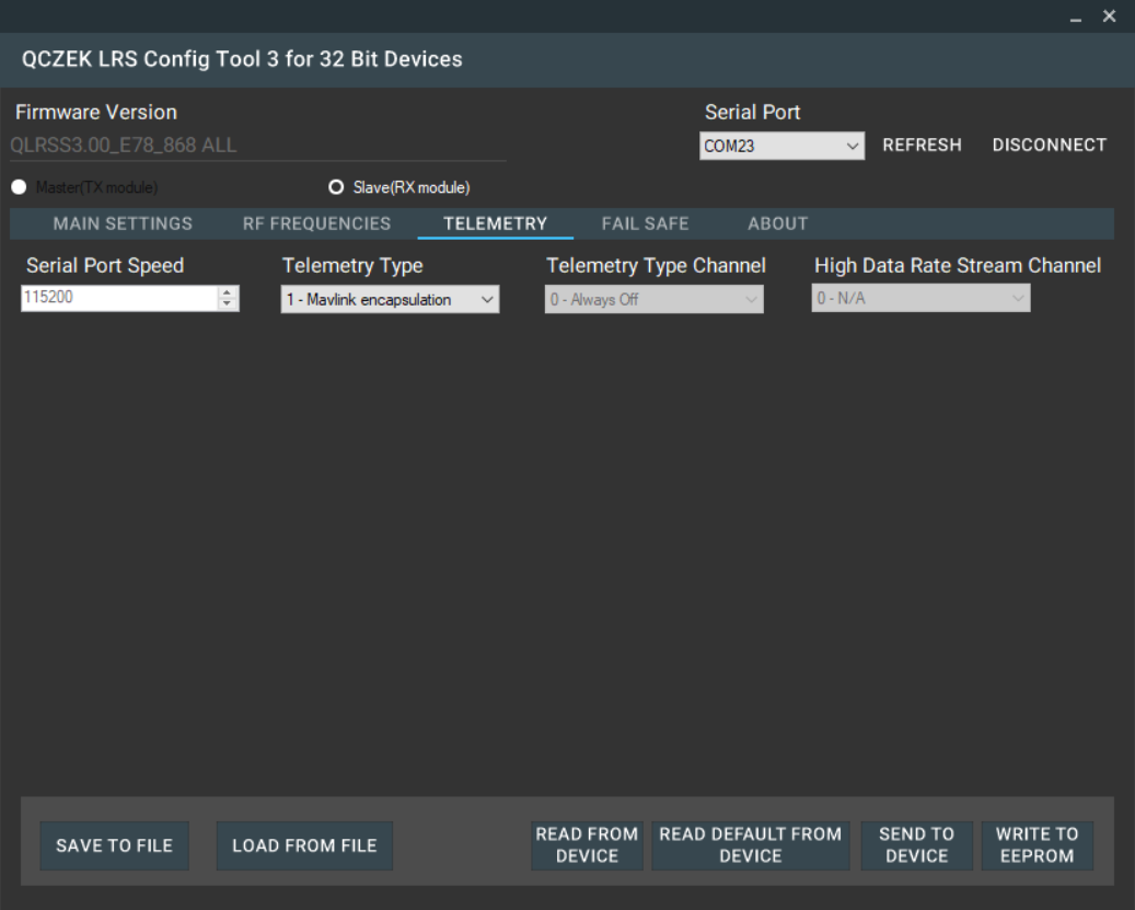
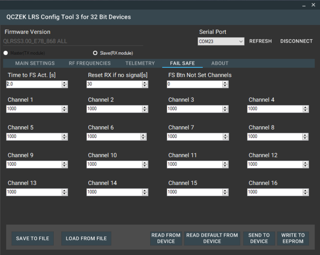
My setting for your reference…
Then it’s time to connect to your FC. Just use some free FC serial port and choose CRSF as radio protocol. Something like this for arduplane FC.
SERIAL4_PROTOCOL = 23
RSSI_TYPE = 3
And it should works 🙂
MASTER (TX) module connection
Starting from the firmware version 3.10, you can build master module, and connect it to your favorite radio supporting CRSF protocol. The only think is that you need to build/buy sport converter exactly like described here https://ardupilot.org/plane/docs/common-connecting-sport-fport.html Another thing is power supply which should not exceed 3.3V.
My quick and dirty solution (for firmware development only) is to use cheap RS232 SP3232 TTL, small SMD diode, and AMS1117-3.3V voltage regulator.
Something like this, please do it better, at least add capacitors to the voltage regulator
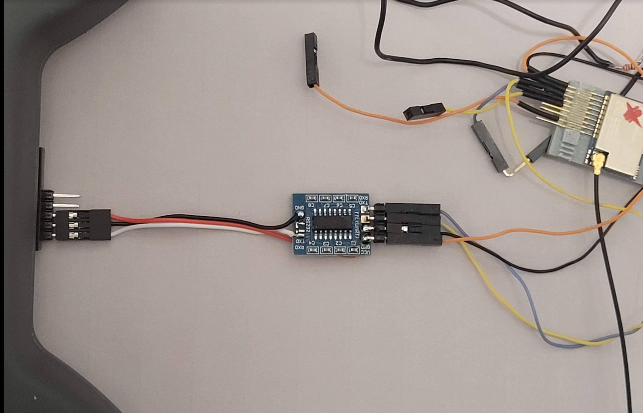
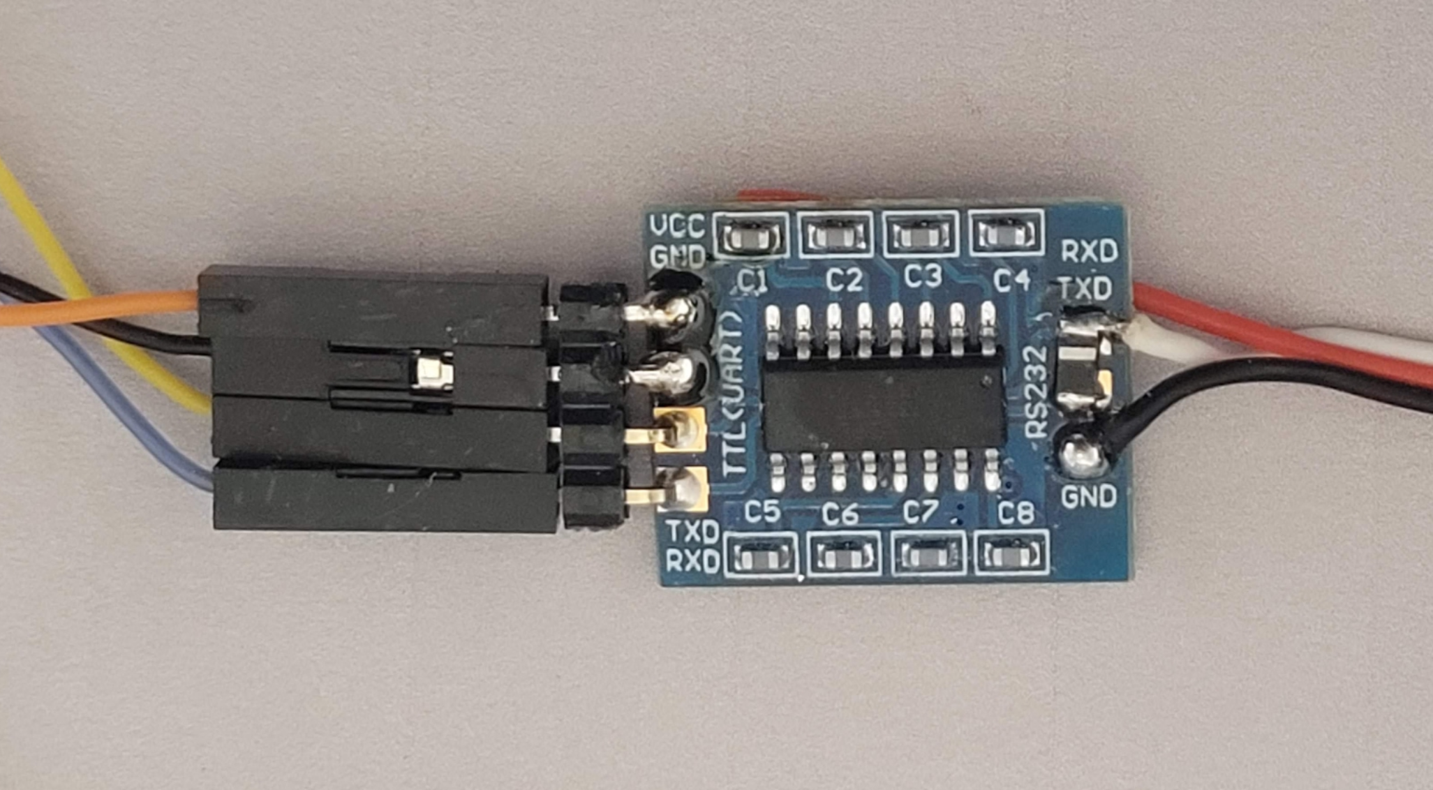

Anyway, the serial port of the ASR module, goes to TTL <-> RS232 converter 🙂
Another thing is settling correct serial port speed, depending on the readio handset you have. My recommendation is to use lover 115k, because it quality of hardware port of the ASR module, is rather low…
Good luck and let me know how it works 🙂