I have spent a lot of time to find out how to upload/debug your firmware to CDEBYTE E78-868LN22S modules, which are based on ASR6501 chip, which included PSOC 4 MCU (compatible with CY8C4147AZI-S445) and Lora SX1262 radio.
The MCU is Cortex M0 running at 48Mhz, 16kB RAM and 128KB flash memory (as far as i know).
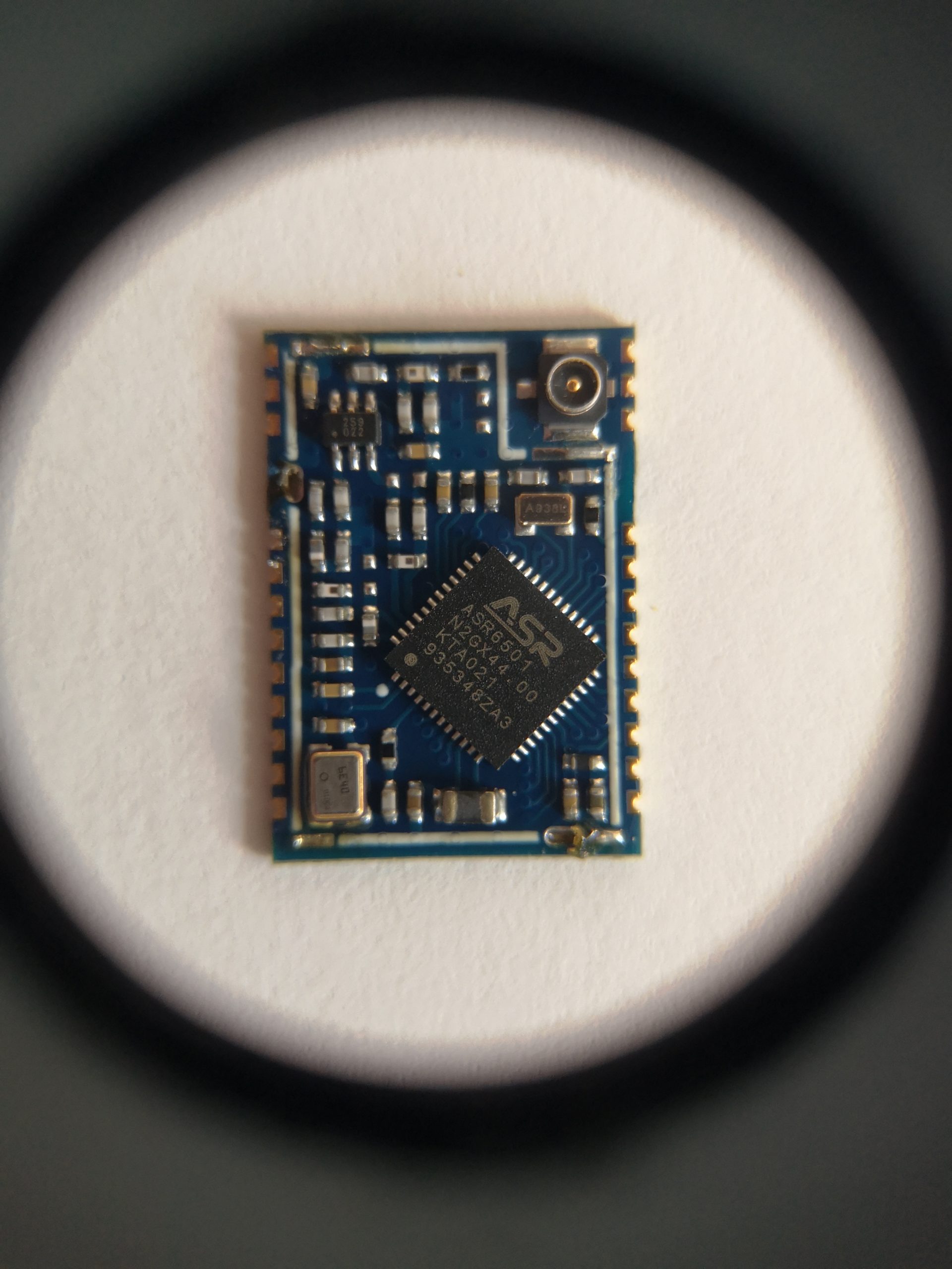
After de soldering a shielding it looks like following
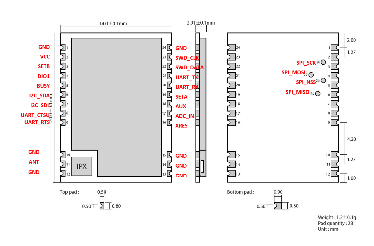
And according to provided documentation we have SWD interface available
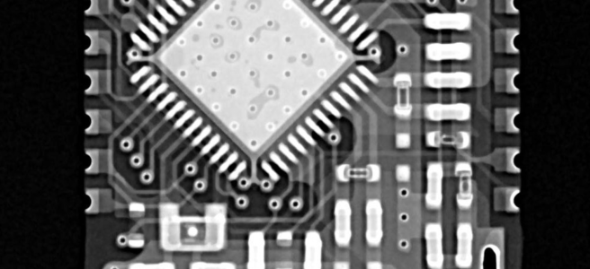
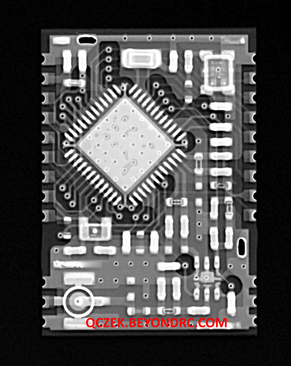
Actually I did not investigate whole pin mapping, but this x ray photo may be useful. If you would do it please, share with me 🙂
You need to know, that, there is no guaranty, that you will be able to flash you module, because SWD interface may be killed by a manufacture. I have talked to CDEBYTE, and they said that starting from some batch, the interface is not killed, so theoretically it’s possible to flash your firmware. The problem is that existing firmware set SWD pins to be disabled, and when you will use only RESET and SWD pins, you will not be able to connect. After long reasearch I found a solution:
It’s simply, you need to synchronize powering the module with reset signal. If it would be fast enough existing firmware will not be able to disable SWD interface.
So first you need KITPROG 3 compatible programming device (KITPROG 2 would not work!). I bough a CY8CKIT-149 prototyping kit and it works fine. But before you start, you need to remember that the E78 module required 3.3V power supply not 5V which is provided by KITPROG3 (but i have a info from one guy that he use 5V for programming and it’s ok, but it’s not recommended). The kitprog uses VTARG pin to detect what is your target voltage, and to adjust IO pins voltage accordingly. I also provides 5V from USB socket via D1 diode, so you can power 5V capable kits directly from the VTARG pin.
So fist thing you need to do is the D1 removal. It would remove 5V voltage from the VTARG pin, but you will need to use external 3.3V power supply. If you are looking quick and dirty solution you can just replace the D1 diode by red LED diode, which will limit VTARG voltage to something like 3.5V. Please note that it’s ok up to few mAmps which can be provided to VTARG pin, but it’s more then enough to program the E78 module.

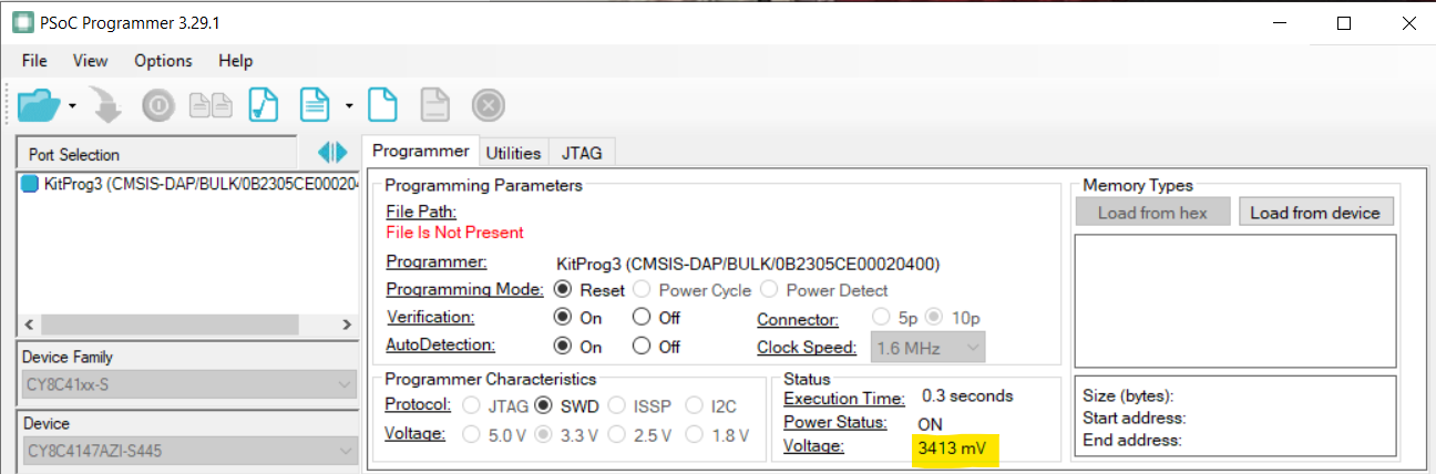
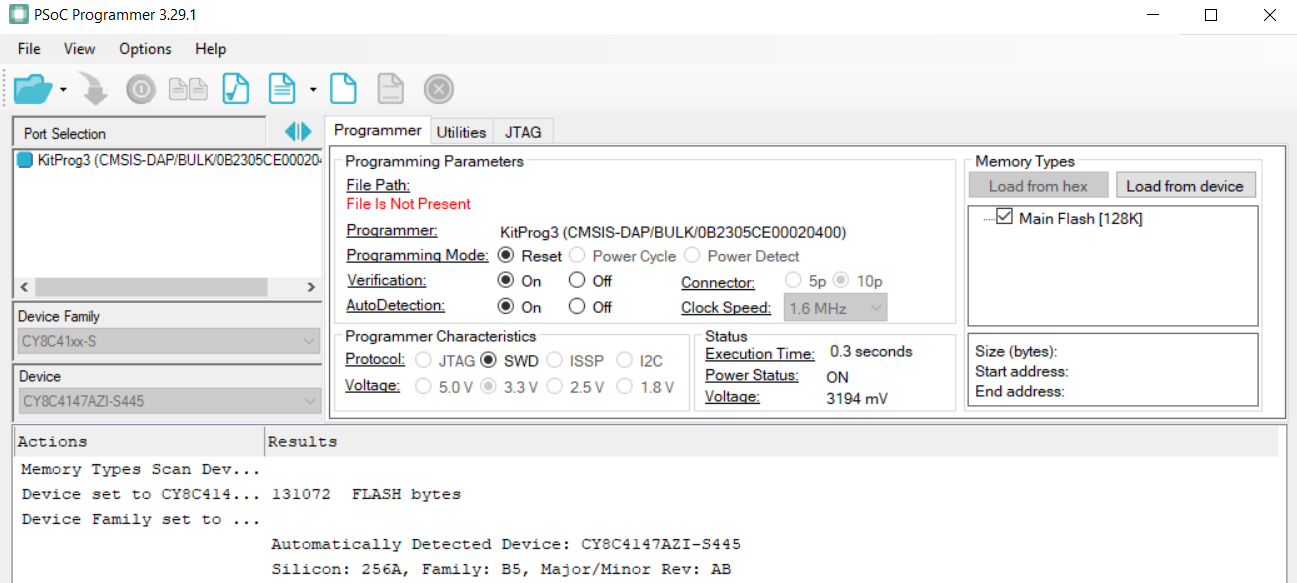
Then you can connect the boadr to your PC run PSOC Programmer software, upgrade kitprog3 firmware if required and you should see something like 3.4V voltage
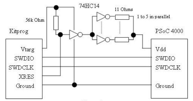
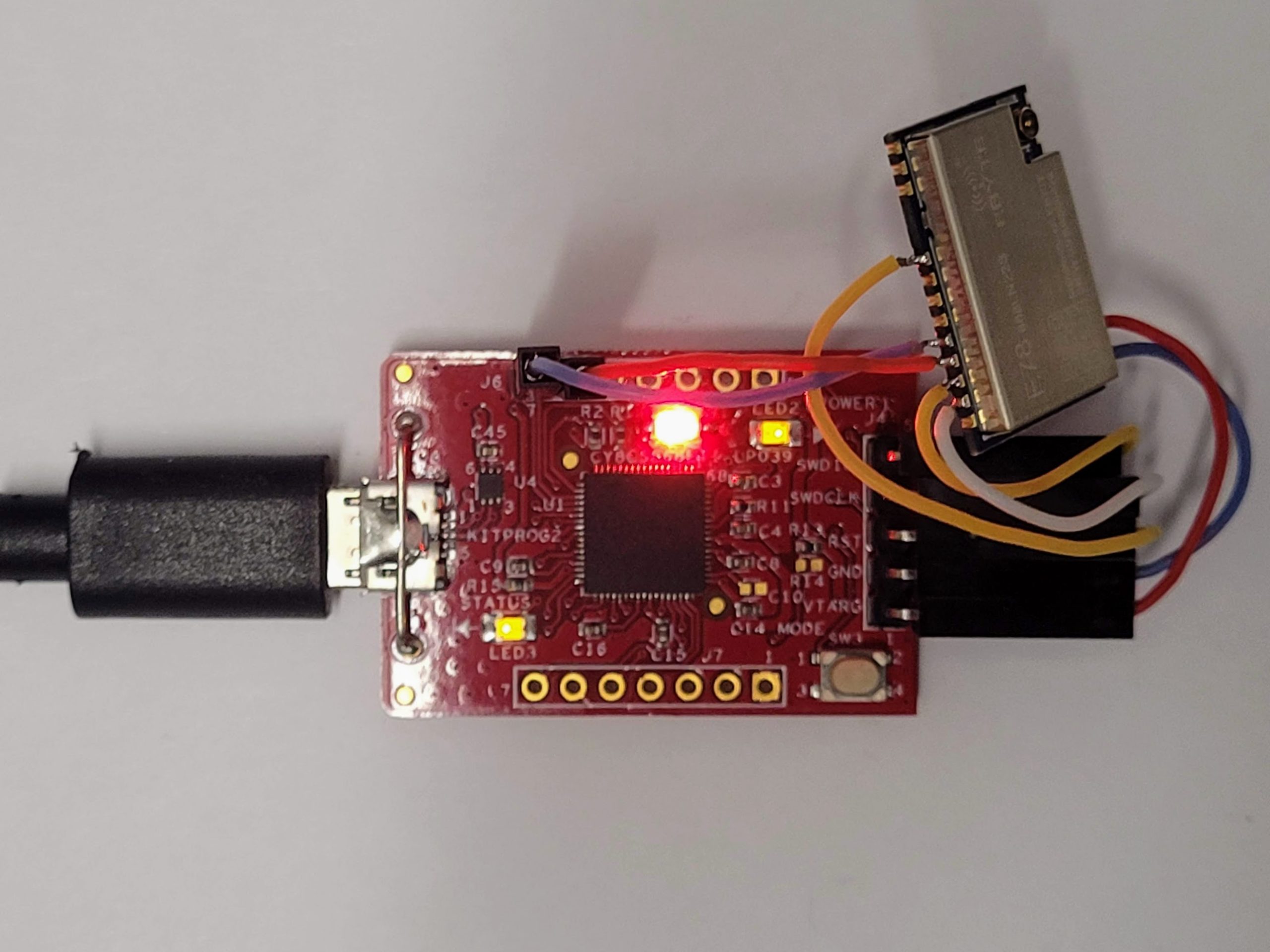
Then you have to build simple circuit according to the picture from the post above.
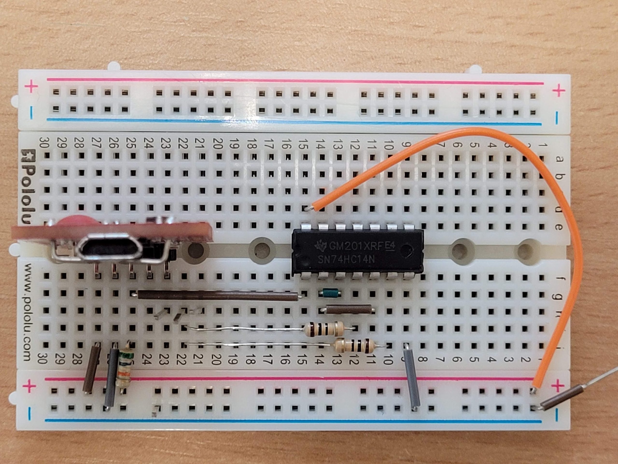
I did something like this
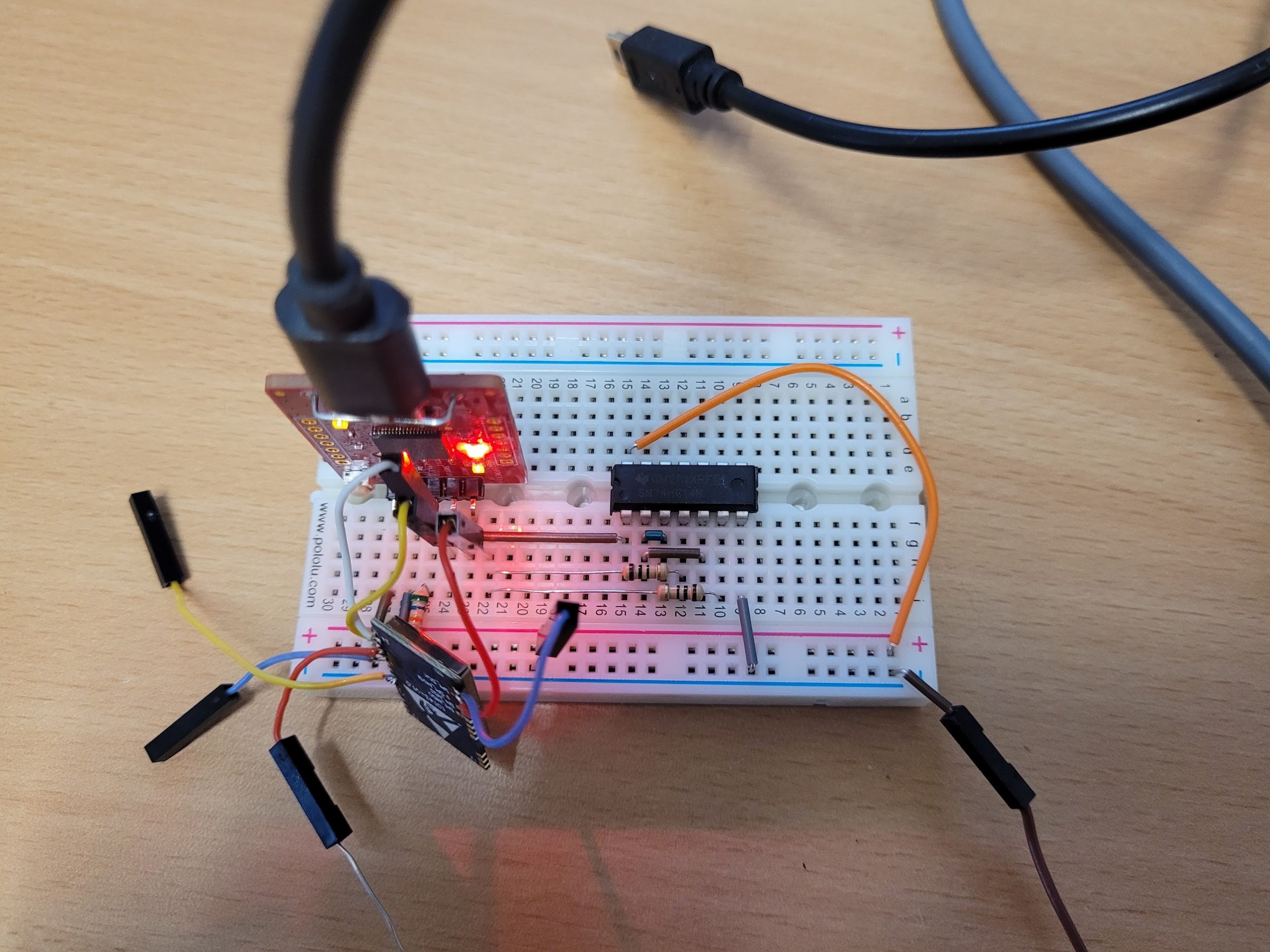
Then connect your E78 module just GND, VCC, SWDCLK, SWDIO, (RESET pin is not required) and run PSOC programmer again and press “Load from device” button. You should get info about connected MCU and flash memory 🙂
Now you can erase the flash from Utilities tab, or just compile anything for your MCU using PSoc Creator and upload.
If you do it, next time, you would not need to use additional circuit, just connect the E78 module directly to kitprog (remember about the reset pin this time) and you will be able to do everything without any problem.
Good luck!
Very informative, Thank you for sharing!
Hey, i work on your qczeck concept for 433MHz module.. but ebyte was upgrading the modul from SWIM flashing mode to be SWD flashing mode.. is there any help to flash the module to be qczeck receiver? Btw i used e32 433t20d/433t20dc module
Hello,
Your projects that shared are really fantastic.
I am especially interested in one of them that is ‘ SX1278 Lo-Ra module (433MHz) , with integrated 30dBm (1W).
But I couldn’t find any schematics on your pages. How did you make your module design? Could you please share with me your schematic? i am wondering what are included this module ? which are passive and active components and their values in your design?
By the way, I have looked into semtech and E-byte website. But they have not shared 1W Lo-Ra module data.
I would be very happy if you could help me. My e-mail adress: tgcerl@gmail.com
i will send an email to you.
Kris
hello ,i’m working also on this module E32 433T20D and i can’t send any message from it to another E32
i need your help please .
my email:feridataher@gmail.com
Hello,
I read your projects and they are really very good. I am also interested in Ebyte E32 1W modules. I am trying to RF power harwest from them. I use 1W E32 module as TX and send dummy massages from UART with arduino. But there is a little interrupt between message packages. This also causing small interrupt at power harwesting side. I write to ebyte but they can not help me. They said to change cpmmunication speed and datarates. I tried all possible combinations but could not fix issue. I think this interrupt caused by MCU inside E32 module. I want to reprogram E32 module for just send dummy message without any interrupt. I have checked your E32 telemetry project. You shared only hex files. Can you share project files for recodding them for my project?
Thank you.