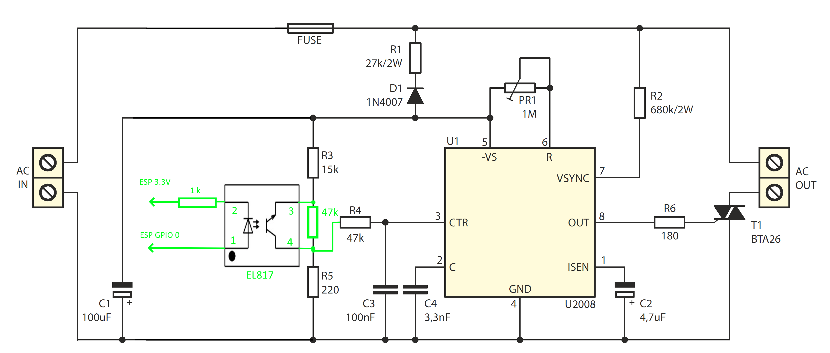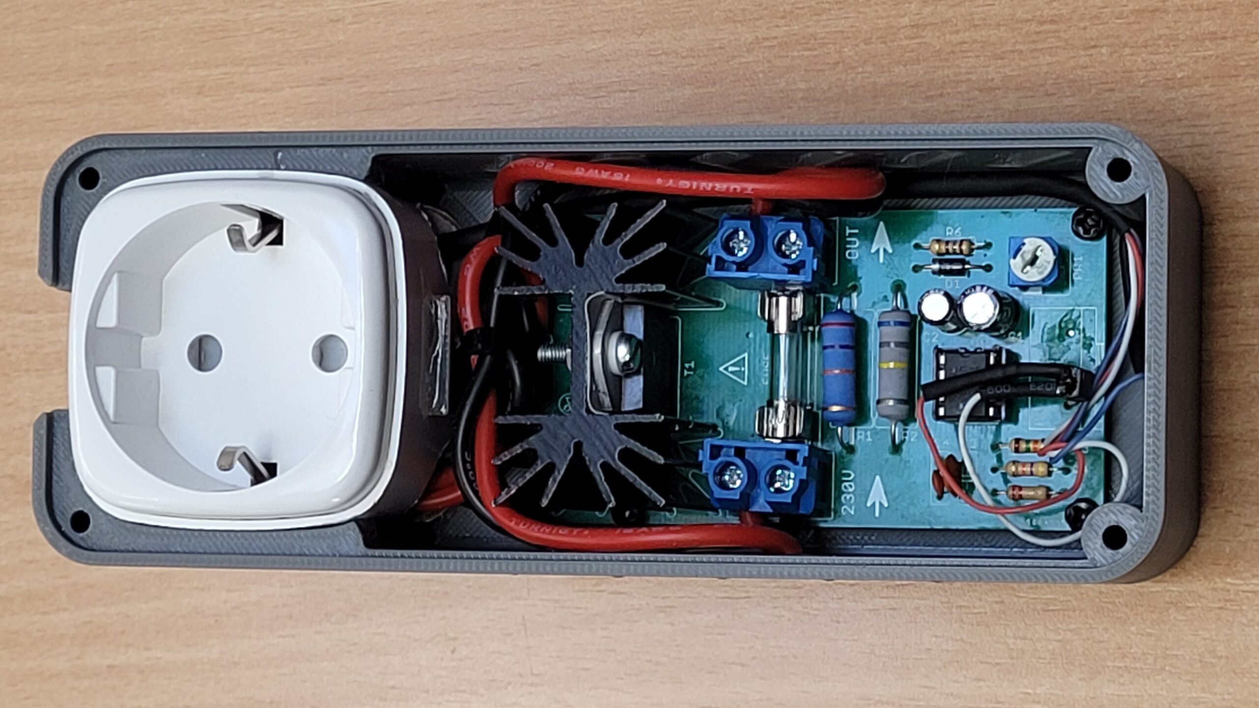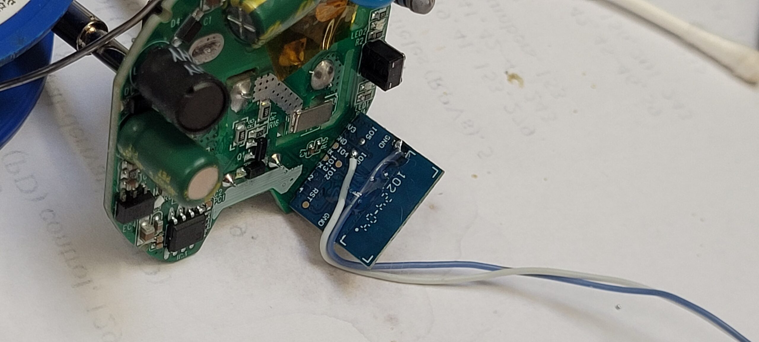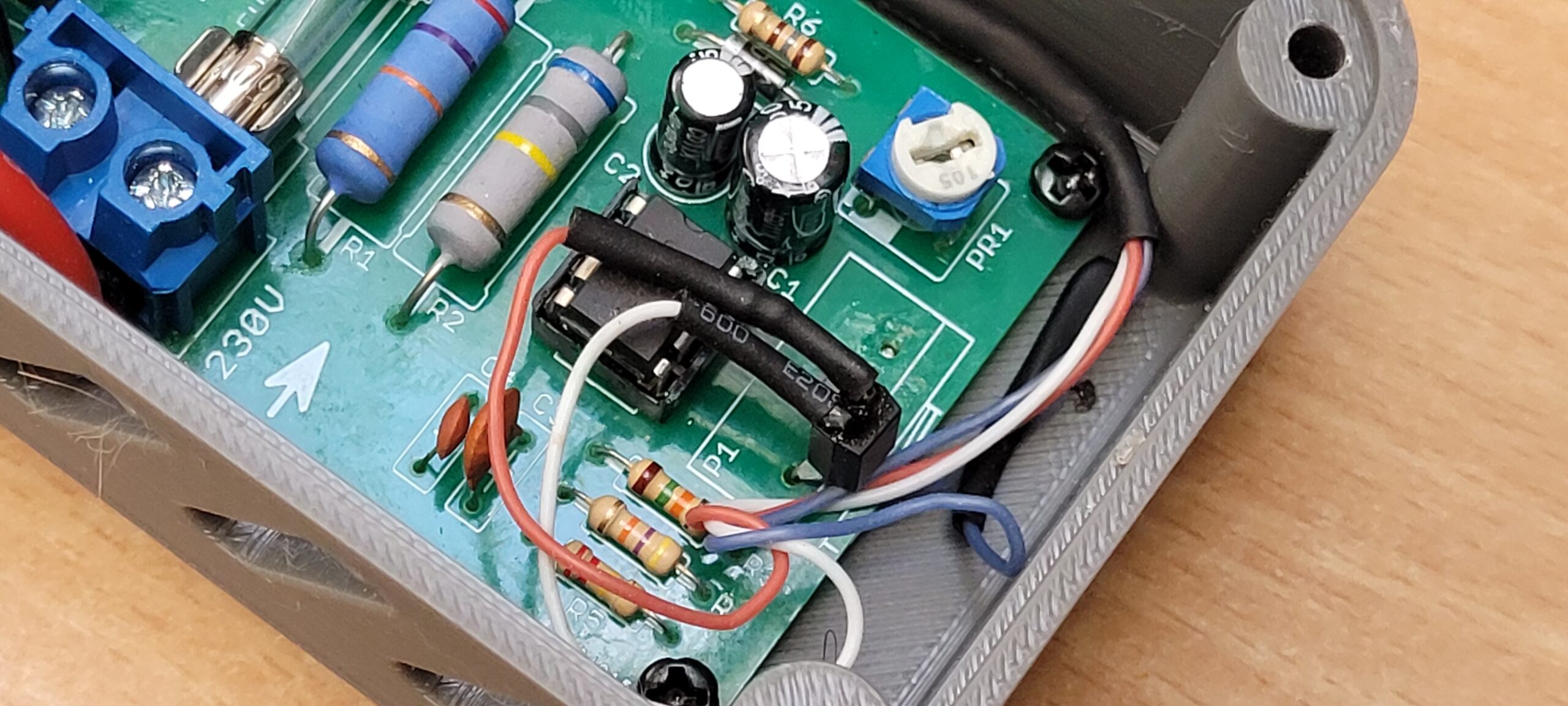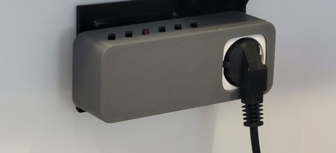
This is a method to convert a Tasmota-based smart plug into a power regulator. I used the AVT 1860 kit as the output component, replacing the potentiometer with an optocoupler. The optocoupler is driven by the unused ESP GPIO 0. You can find the schematic and a few photos below.
I’m not providing a detailed description because if someone isn’t knowledgeable enough to do it themselves, they should probably not attempt it at all. The circuit involves high voltage, which is dangerous. It should also be enclosed in a housing made of non-flammable material—for example, a housing printed from flame-retardant filament (FR).
In Tasmota, you need to set GPIO 0 to the PWM function and disable the LedTable option by setting it to zero.
Good luck!