
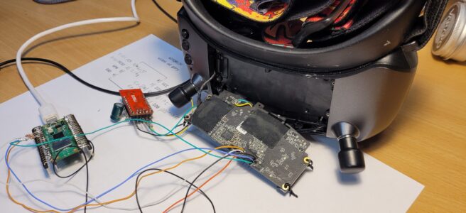
I recovered a Walksnail Avatar Goggles X after an incompatible firmware image and a forced DDR change replaced low-level boot components. The SoC ROM still executed, but the resulting SPL could no longer initialise the on-board QSPI flash. This repair used direct in-circuit access to the Winbond W25Q01JV with a Raspberry Pi Pico running pico-serprog, then restored only enough of the boot chain for the official Avatar X updater to finish the job.
This is a repair log, failure analysis and reproducible recovery guide for the specific hardware and firmware I investigated. Verify every offset and binary against your own board revision before writing anything.
Warning: direct flash access can destroy the board
- This procedure can permanently brick or electrically damage the goggles.
- The flash uses 3.3 V logic. Never apply 5 V to it.
- Disconnect the goggles’ normal battery/input power while directly powering the flash rail.
- Power the Pico independently over USB and connect Pico ground to target ground.
- Do not connect the Pico 3V3 pin to the target when using the external 3.3 V supply.
- The shared target 3.3 V rail can power other circuitry, not only the flash.
- Use short wires, start at a conservative SPI clock and verify repeated reads by hash before writing.
- Restrict every write to an explicit flashrom layout region whenever possible.
- Never perform a chip erase for this recovery. Make backups before modifying anything.
How the goggles were bricked
The goggles worked normally before the incident. I accidentally flashed firmware intended for another hardware configuration and forced the DDR change. The broken SPL identified itself as:
U-Boot SPL 2017.07Arto (Apr 18 2026 - 10:54:14)It configured DDR4 at 2133 MHz with a 32-bit bus. The correct Avatar X configuration is DDR4 at 2400 MHz, also 32-bit. The first failure was:
Trying to boot from emmc_and_qspi
Read flash ID: 2140ef
QSPI: unrecognized JEDEC id: ...
probe spi device failed!
SPL: failed to boot from all boot devices
This was an important diagnostic clue: the SoC ROM executed and DDR initialised, but the low-level boot firmware could no longer initialise the QSPI flash correctly. The repair therefore had to begin below Linux and below the normal firmware updater.
The flash device
The mainboard uses a Winbond W25Q01JV / W25Q01JVIQ: a 128 MiB, 3.3 V SPI NOR device in a WSON-8 package. Its JEDEC ID is EF 40 21. flashrom 1.8.0 reports:
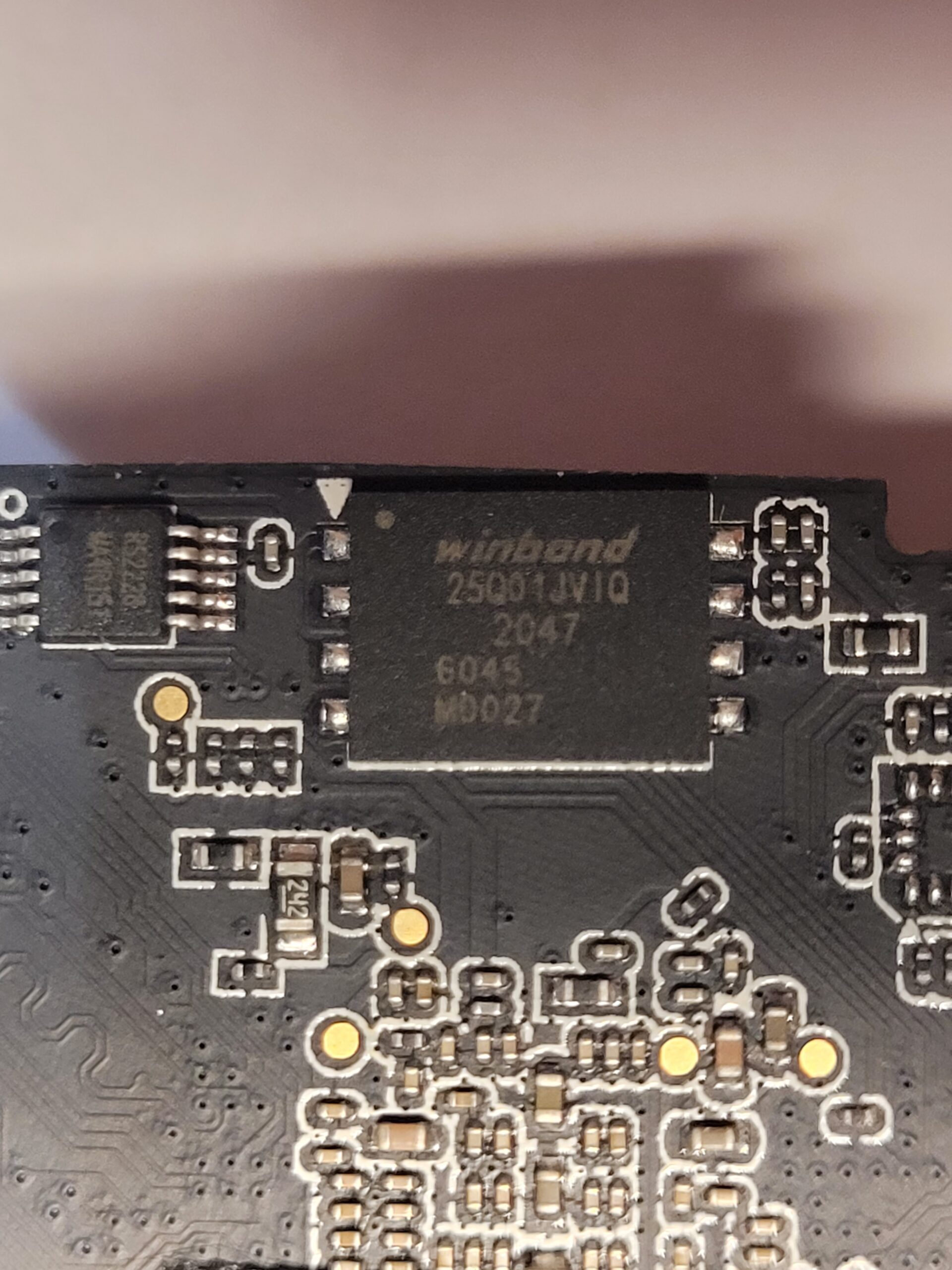
Found Winbond flash chip "W25Q01JV" (131072 kB, SPI) on serprog.| Pin | Signal | Function |
|---|---|---|
| 1 | /CS | Chip select |
| 2 | DO / IO1 / MISO | Data output |
| 3 | WP# / IO2 | Write protect / quad I/O |
| 4 | GND | Ground |
| 5 | DI / IO0 / MOSI | Data input |
| 6 | CLK | SPI clock |
| 7 | HOLD# / RESET# / IO3 | Hold/reset / quad I/O |
| 8 | VCC 3.3 V | Supply |
This table is a top-view pinout. The package dot or mark identifies pin 1.
Pico-serprog wiring
I used a Raspberry Pi Pico running opensensor/pico-serprog. The following table records the actual wiring. WP# and HOLD#/RESET# were already pulled high on the target board and were not driven by the Pico during normal programming.
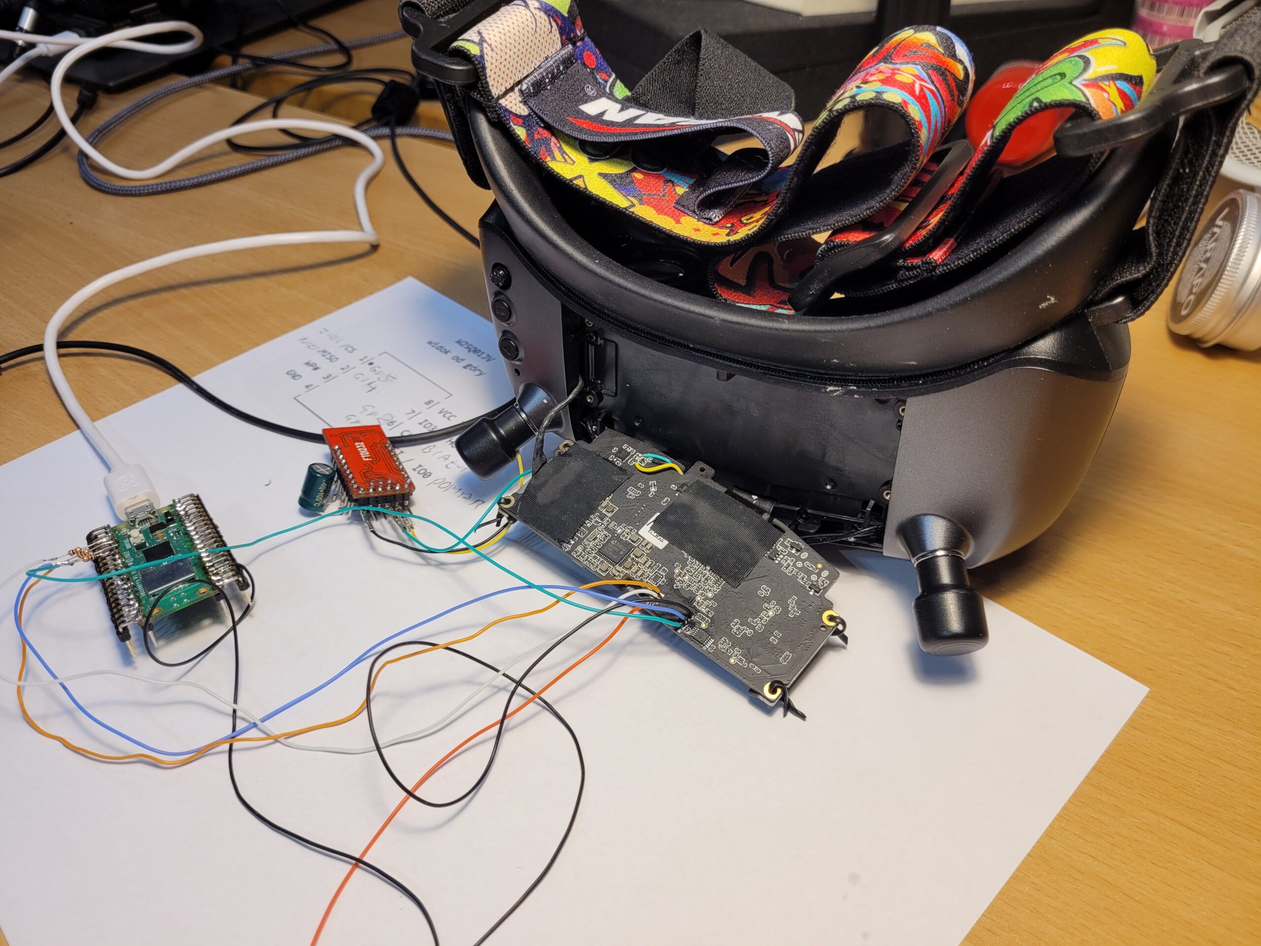
| Flash pin | Signal | Pico GPIO | Series resistor | Notes |
|---|---|---|---|---|
| 1 | /CS | GP5 | ~1 kΩ | Chip select |
| 2 | MISO | GP4 | ~1 kΩ | Flash to Pico |
| 5 | MOSI | GP3 | ~1 kΩ | Pico to flash |
| 6 | CLK | GP2 | ~1 kΩ | SPI clock |
| 4 | GND | GND | None | Common ground |
The approximately 1 kΩ series resistors in the SPI signal lines help limit contention with circuitry that remains connected to the shared bus. They add a useful margin of safety during in-circuit experiments, although they do not replace careful power and signal-integrity checks.
Powering the flash rail
The Pico must not power the target from its 3V3 output. I powered the Pico independently over USB and used a laboratory bench supply set to 3.3 V for the target flash/3.3 V rail. Pico 3V3 was left disconnected, the grounds were joined, and normal goggles battery/input power was disconnected.
The in-circuit rail drew approximately 113 mA. That is far more than a bare idle flash device and showed that the supply was back-powering part of the goggles electronics. Anyone repeating this work must treat the connection as power to a shared board rail, not power to an isolated memory chip.
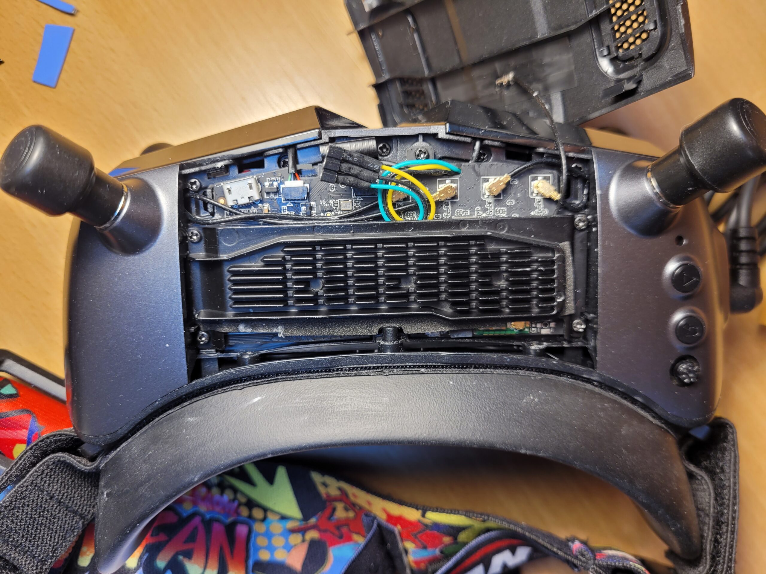
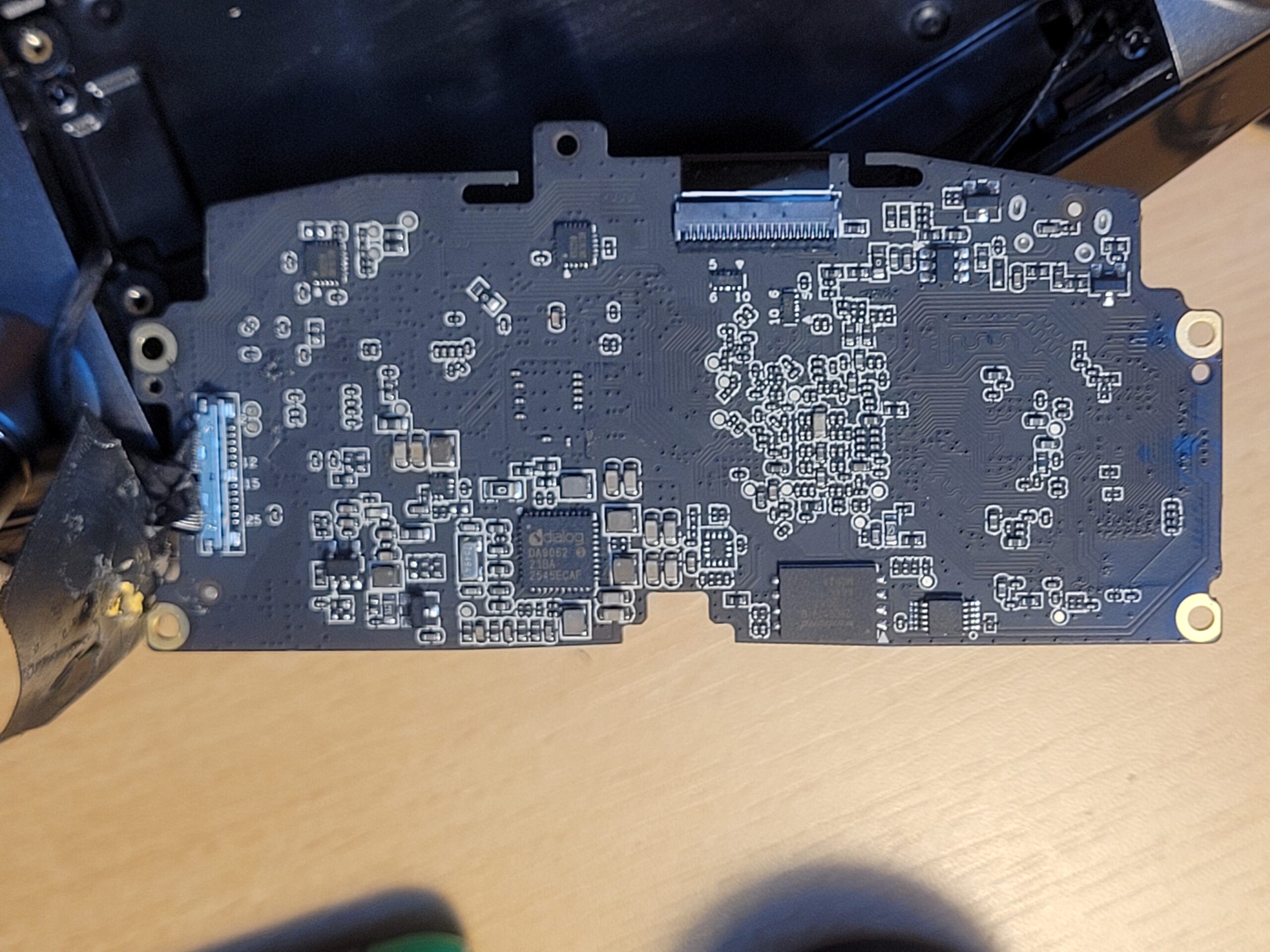
This photograph shows the permanent UART/serial debug lead, not the SPI programmer connection.
Host software and reliable SPI speed
The host was Windows with MSYS2 UCRT64, flashrom 1.8.0, and the Pico running opensensor/pico-serprog. My initial conservative command was:
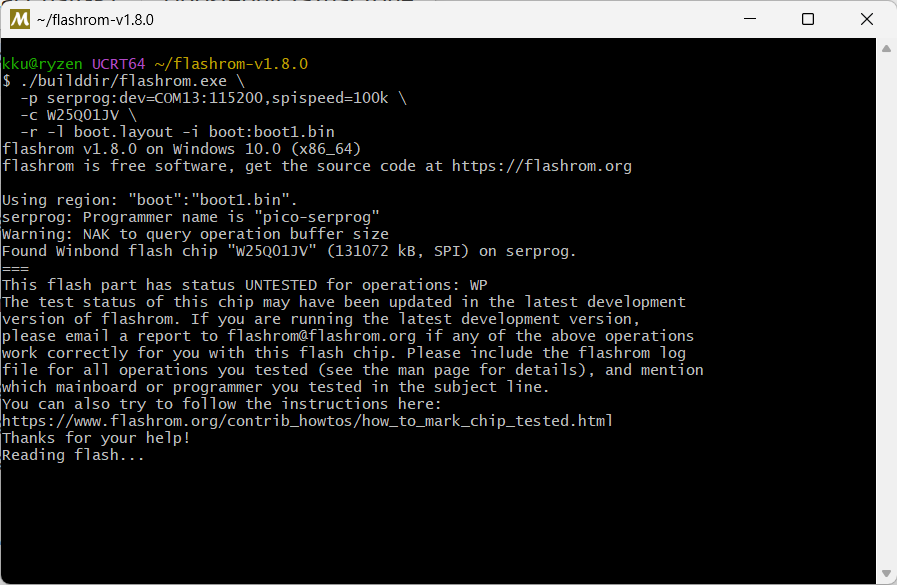
./builddir/flashrom.exe \
  -p serprog:dev=COM13:115200,spispeed=1M \
  -c W25Q01JV
Although the programmer appears as a serial COM port, pico-serprog uses USB CDC. The 115200 parameter is therefore not the actual limiting UART speed. I began programming at 1 MHz. Later, 8 MHz was stable for full-flash reads; at 16 MHz the flash was no longer detected reliably with my in-circuit wiring. The practical ceiling depends heavily on wire length, board loading and signal integrity.
Stage 1: recover only the boot region
The first repair targeted only 0x000000-0x10FFFF, a total of 0x110000 bytes (1,114,112 bytes). It contains:
| Range | Component | Size |
|---|---|---|
0x000000-0x00FFFF | ROM code | 64 KiB |
0x010000-0x08FFFF | SPL0 | 512 KiB |
0x090000-0x10FFFF | SPL1 | 512 KiB |
I built a recovery image from a known-correct Avatar X firmware and described the permitted write range in boot.layout:
00000000:0010ffff bootThe write command was:
./builddir/flashrom.exe \
  -p serprog:dev=COM13:115200,spispeed=1M \
  -c W25Q01JV \
  -N \
  -V -o recovery-write.log \
  -w \
  -l boot.layout \
  -i boot:AvatarX_boot_recovery_0x110000.bin
flashrom completed with VERIFIED. On the next boot the SPL was the correct build:
U-Boot SPL 2017.07Arto (Jan 23 2025 - 17:10:02)

DDR init:
type 4
freq 2400
width 32

Read flash ID: 2140ef
Name: w25q01jviq
spi nor flash init success
This restored DDR and QSPI initialisation, but it did not yet recover the goggles.
Stage 2: find the incompatible full U-Boot
The repaired SPL successfully loaded the second-stage bootloader, but the active full U-Boot was still the incompatible build:
U-Boot 2017.07Arto (Apr 18 2026 - 10:54:14 +0800)It again failed to initialise the W25Q01JV. Reading both physical U-Boot slots showed:
| Slot | Physical range | Result |
|---|---|---|
| uboot0 | 0x740000-0x7BFFFF | Correct 10:48:27 build; contained w25q01jviq support |
| uboot1 | 0x7C0000-0x83FFFF | Active incompatible 10:54:14 build |
I copied the good uboot0 image to uboot1. The next log showed:
U-Boot 2017.07Arto (Apr 18 2026 - 10:48:27 +0800)

Read flash ID: 2140ef
Name: w25q01jviq
The system could now continue into the Linux kernel.
Stage 3: let the official updater repair the mixed state
Linux and GlassesUI booted, but the displays remained black and the LEDs did not work. The log also contained hardware/configuration-related messages, including missing GPIO and PWM resources. This showed that the flash still held a mixture of partitions from the incompatible firmware and the correct Avatar X firmware.
Once the correct U-Boot could access QSPI normally, I inserted a USB drive containing the official Avatar X firmware 39.44.18 and allowed the built-in updater to complete the remaining partition updates. After the official update, the displays, LEDs and GUI all worked, and the firmware reported version 39.44.18.
The distinction matters: the manual procedure restored only enough of the boot chain for the official updater to work again. It was the complete official update that restored the remaining hardware-specific software state.
Physical layout of the working 128 MiB flash
| Offset | Size | Size (human) | Partition |
|---|---|---|---|
0x000000 | 0x010000 | 64 KiB | romcode |
0x010000 | 0x080000 | 512 KiB | spl0 |
0x090000 | 0x080000 | 512 KiB | spl1 |
0x110000 | 0x010000 | 64 KiB | gpt |
0x120000 | 0x200000 | 2 MiB | factory |
0x320000 | 0x380000 | 3.5 MiB | logo |
0x6A0000 | 0x010000 | 64 KiB | env0 |
0x6B0000 | 0x010000 | 64 KiB | env1 |
0x6C0000 | 0x040000 | 256 KiB | optee0 |
0x700000 | 0x040000 | 256 KiB | optee1 |
0x740000 | 0x080000 | 512 KiB | uboot0 |
0x7C0000 | 0x080000 | 512 KiB | uboot1 |
0x840000 | 0x800000 | 8 MiB | kernel |
0x1040000 | 0x010000 | 64 KiB | dtb0 |
0x1050000 | 0x010000 | 64 KiB | dtb1 |
0x1060000 | 0xD00000 | 13 MiB | userapp0 |
0x1D60000 | 0xD00000 | 13 MiB | userapp1 |
0x2A60000 | 0xF00000 | 15 MiB | uiapp |
0x3960000 | 0x600000 | 6 MiB | a7_rtos |
The partitioned area ends at 0x03F60000. The remainder of the 128 MiB chip was 0xFF in the captured working dump.
Create a full working backup
After the goggles were fully working, I read a complete 128 MiB “golden” dump at the stable 8 MHz SPI speed:
./builddir/flashrom.exe \
  -p serprog:dev=COM13:115200,spispeed=8M \
  -c W25Q01JV \
  -V -o full-read.log \
  -r AvatarX_full_working_39.44.18-flash_dump.bin
The expected file size is 134217728 bytes. The SHA-256 of my working dump is:
e591ff3f944529d2c8adea1b9ea04e32d5e398314b2f61684bd7da74a80ff2a7This hash identifies the dump from my device. It is not a universal firmware hash, and the dump is intentionally not offered for download.
Why a raw dump is not the official upgrade image
The official .img file is an update package. It contains an OTRA header, hashes, an RSA signature, partition or segment metadata, compressed payloads and instructions that control updater behaviour.
A raw 128 MiB read is the actual state of one physical pair of goggles: boot firmware, GPT, factory data, current environment, both A/B slots, filesystem state, runtime-modified files, device-specific information and unused flash space. It therefore contains data that is not present in the updater image.
In particular, the factory partition may hold calibration data, hardware configuration, MAC or device identifiers, and serial or other unit-specific values. Readers should create and protect their own dump rather than copying one from another device.
Recovery sequence
- The wrong firmware replaced low-level boot components.
- The SoC ROM still ran, but the broken SPL could not access QSPI correctly.
- I established direct access to the W25Q01JV with a Raspberry Pi Pico and pico-serprog.
- I recovered the restricted low-level boot region.
- A second incompatible U-Boot was then found in the active A/B slot.
- I replaced the active U-Boot with the known-good version.
- The goggles booted far enough for the official 39.44.18 updater to run.
- The official update restored the remaining hardware-specific partitions and functions.
- I saved a complete 128 MiB working flash dump for future analysis.
The exact offsets and recovery binaries are specific to the hardware and firmware examined here. Confirm the flash identity, board revision, slot contents and every layout boundary before applying this procedure to another revision.
You Sir are definitely a king, will post your website and video to my friends YT channels who do revisions of FPV stuff but this magically unbricking for me as a programmer and by using Pico board is just next-level. Congrats on your effort and hope to see more customizations from you especially when it comes to a poor debug information that Caddx provides when we switch Debug on usually to follow the temperature range on the glasses.
Cheers,
Mickey, Serbia
thank you 🙂